

Antenna device and base station device
An antenna device and base station technology, which is applied to antennas, antenna parts, diversity/multi-antenna systems, etc., can solve problems without any ground considerations, and achieve the effect of high-efficiency data transmission
- Summary
- Abstract
- Description
- Claims
- Application Information
AI Technical Summary
Problems solved by technology
Method used
Image

Examples
no. 1 approach
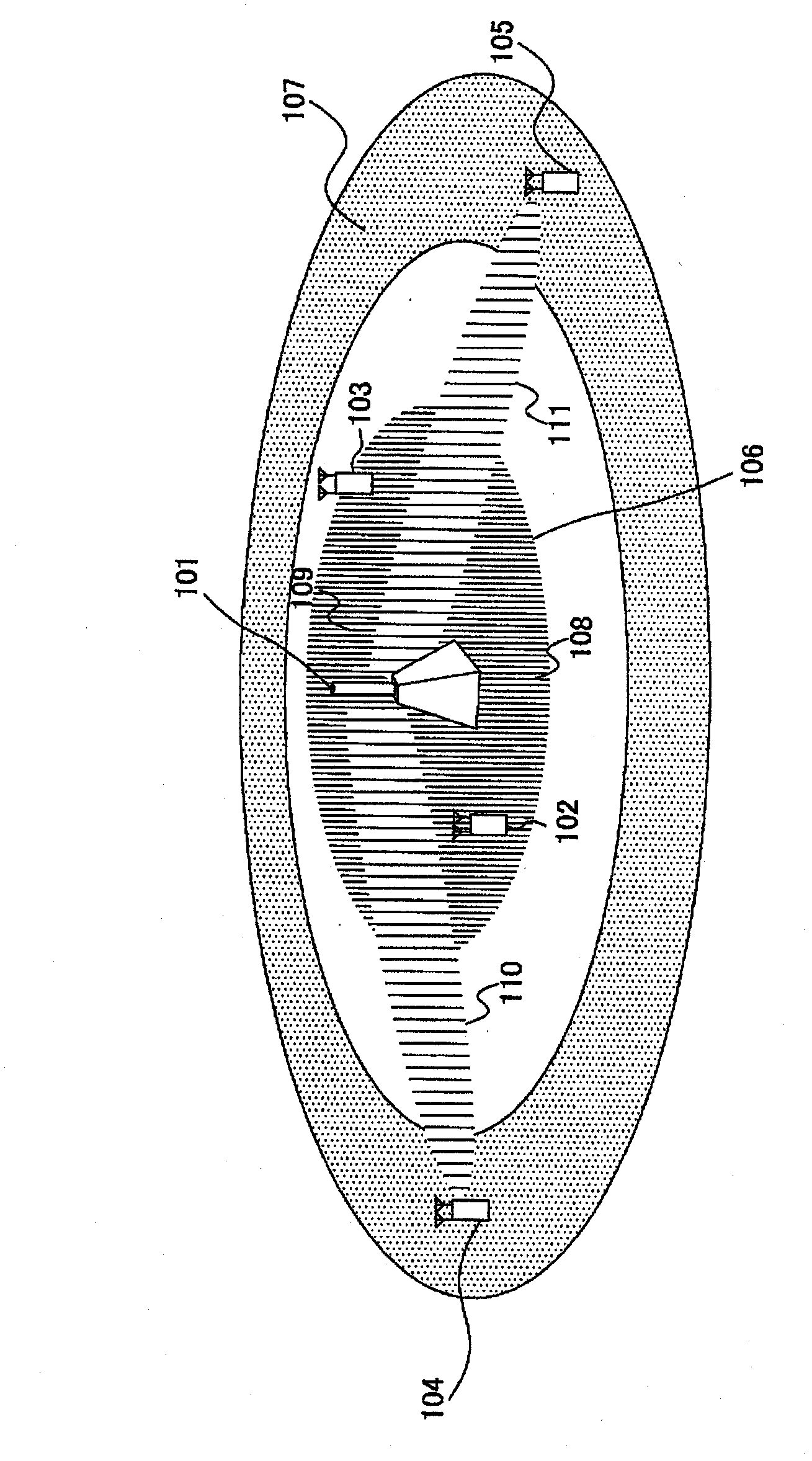
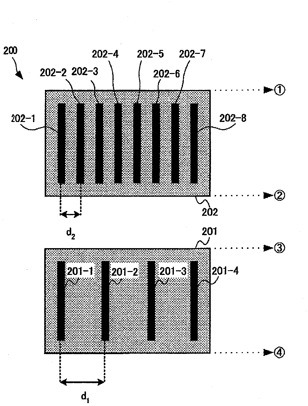
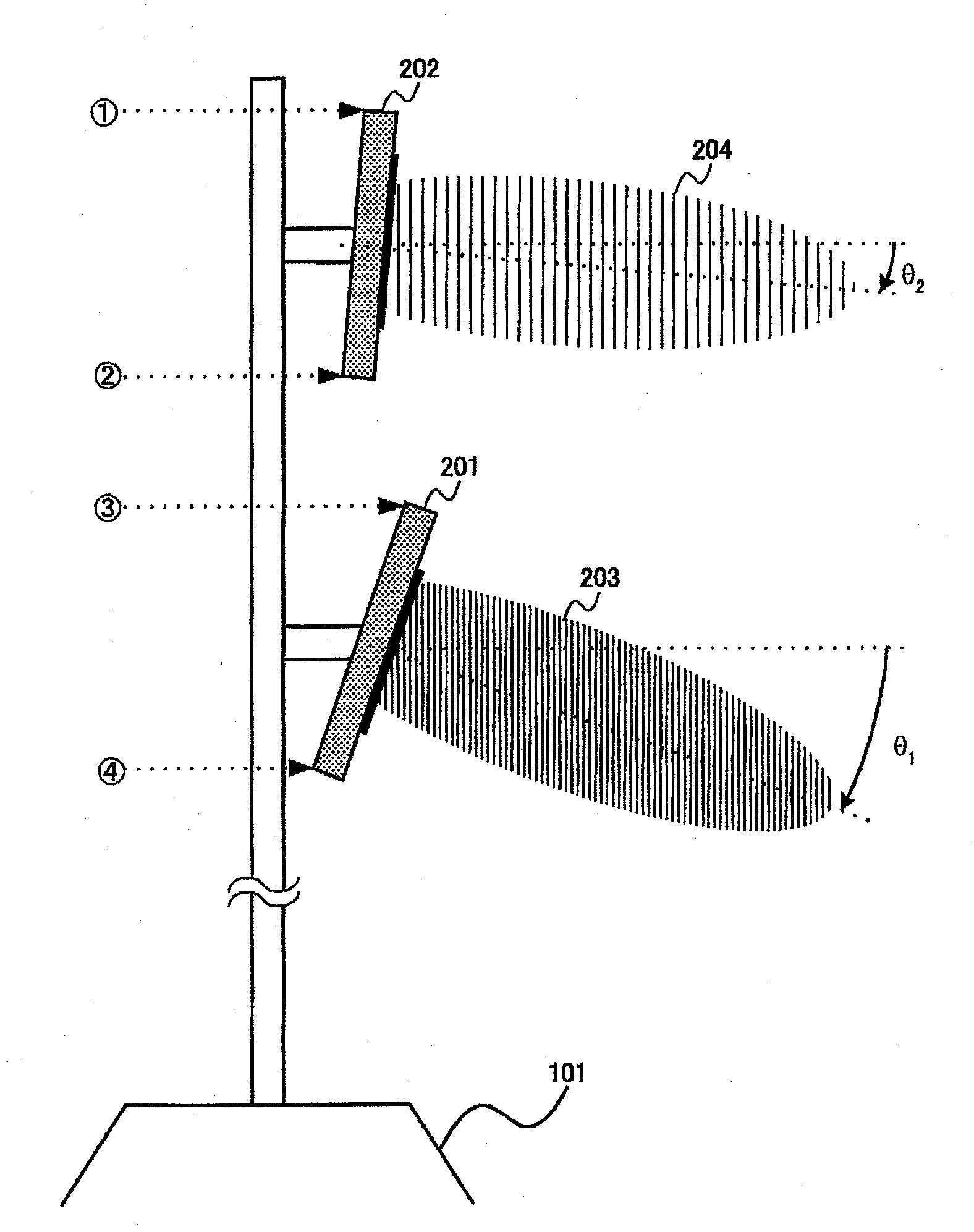
[0057] An example of antenna tilt suitable for a case where different array antennas are used according to transmission modes in the first embodiment will be described. Figure 2A with Figure 2B It is a diagram showing an example of the transmission antenna device (antenna device) 200 of the base station device according to this embodiment. The transmitting antenna device 200 has an array antenna (MIMO array) 201 for MIMO mode transmission and an array antenna (BF array) 202 for BF mode transmission. Add θ to the MIMO array 201 in the elevation direction 1 , and add θ to the BF array 202 in the elevation direction 2 The inclination angle (down-tilt angle). At this time, the θ 1 set to ratio θ 2 A large value (absolute value) (θ 2 can be 0). Thus, beam 203 transmitted from MIMO array 201 is directed toward a mobile station device located closer to the transmitting device than beam 204 transmitted from BF array 202 . In addition, in this embodiment, an example is shown ...
no. 2 approach
[0067] An example in which the antenna is physically tilted in the elevation direction when the downtilt is added in the first embodiment has been described. In this embodiment, each antenna element is further composed of a plurality of elements. Thus, instead of physically tilting the antenna in the elevation direction, the tilt angle is set by giving a phase difference when powering these elements.
[0068] Figure 3A with Figure 3B It is a figure which shows an example of the structure of the antenna element concerning this embodiment. The antenna element 301 further has a plurality of elements 301-1 to 301-3. When power is supplied to the elements 301-1 to 301-3 through the power supply line 302, a phase difference is imparted between 301-1 and 301-2 and between 301-2 and 301-3 by using delay elements 303 and 304 . Accordingly, it is possible to add a tilt angle to the antenna pattern 305 in the elevation direction of the antenna element 301 . Although the interval ...
no. 3 approach
[0073] In the first embodiment and the second embodiment, an example of the configuration of the transmission antenna device was shown. In this embodiment, an example of subframe configurations in the MIMO mode and the BF mode will be used to describe signals transmitted from the MIMO array and the BF array. Figure 5is a diagram showing an example of a downlink subframe configuration. The subframe includes: data channel (PDSCH (Physical Downlink Shared Channel, physical downlink shared channel) or PMCH (Physical Multimedia broadcast multicast service Channel, physical multimedia broadcast multicast service channel)), control channel (PCFICH (Physical Control Format Indication Channel, Physical Control Format Indicator Channel), PHICH (Physical Hybrid automatic repeat request Indicator Channel, Physical Hybrid Automatic Repeat Request Indicator Channel), PDCCH (Physical Downlink Control Channel, Physical Downlink Control Channel)), and synchronization signals and reference sig...
PUM
 Abstract
Description
Claims
Application Information