Data transmission method and data transmission apparatus

Inactive Publication Date: 2005-07-21
SNAPTRACK
View PDF21 Cites 101 Cited by
  • Summary
  • Abstract
  • Description
  • Claims
  • Application Information

AI Technical Summary

Benefits of technology

[0032] According to this invention, the window size, which is the number of data units handled in the predetermined layer, is changed according to the radio wave environment at that time, so that for example the data amount accumulated in the receiving-side buffer can be controlled to be an appropriate amount of data; hence a situation in which received data in the receiving-side buffer is discarded can be prevented, to the extent possible.
[0033] That is, when for example the rate at which correct decoding has not been made is greater than a stipulated value, or the rate at which correct decoding has been made is equal to or less than a stipulated value, as a window size change request, the radio link control layer (RCL layer) protocol is used to issue a request to decrease the window size, so that when the radio wave environment is not excellent, the amount of data accumulated in the buffer of the RCL layer on the receiving side is decreased, and processing is performed in small data amount units. Accordingly, the occurrence of repeated data transmission and of repeated data discarding due to incomplete received data can be reduced. As a result, degradation of the d

Problems solved by technology

However, in an actual mobile wireless communication system, data transmission errors normally occur due to changes in and degradation of the radio wave propagation environment, as a result of fading, multipath interference, and other causes.
As a result, in cases where the radio wave environment is degraded, there is the problem that a vicious circle may occur in buffer management, with a state arising in which data accumulation and data discarding are repeated in the buffer of the RLC layer.
At this time, as indicated by an “x” symbol in FIGS. 3A to 3J, if correct data reception (decoding) has not been made either on the reception side with respect to the resent retransmitted MAC-hs PDU, similarly to the previous case, NACK data is transmitted fr

Method used


Image

  • Data transmission method and data transmission apparatus
  • Data transmission method and data transmission apparatus
  • Data transmission method and data transmission apparatus

Examples


Embodiment Construction

[0044] Hereinafter, an embodiment of the invention is explained, referring to FIGS. 4 through 7.

[0045] In this example, a configuration is explained in which HARQ (Hybrid ARQ) is applied to HSDPA (High-Speed Downlink Packet Access) methods.

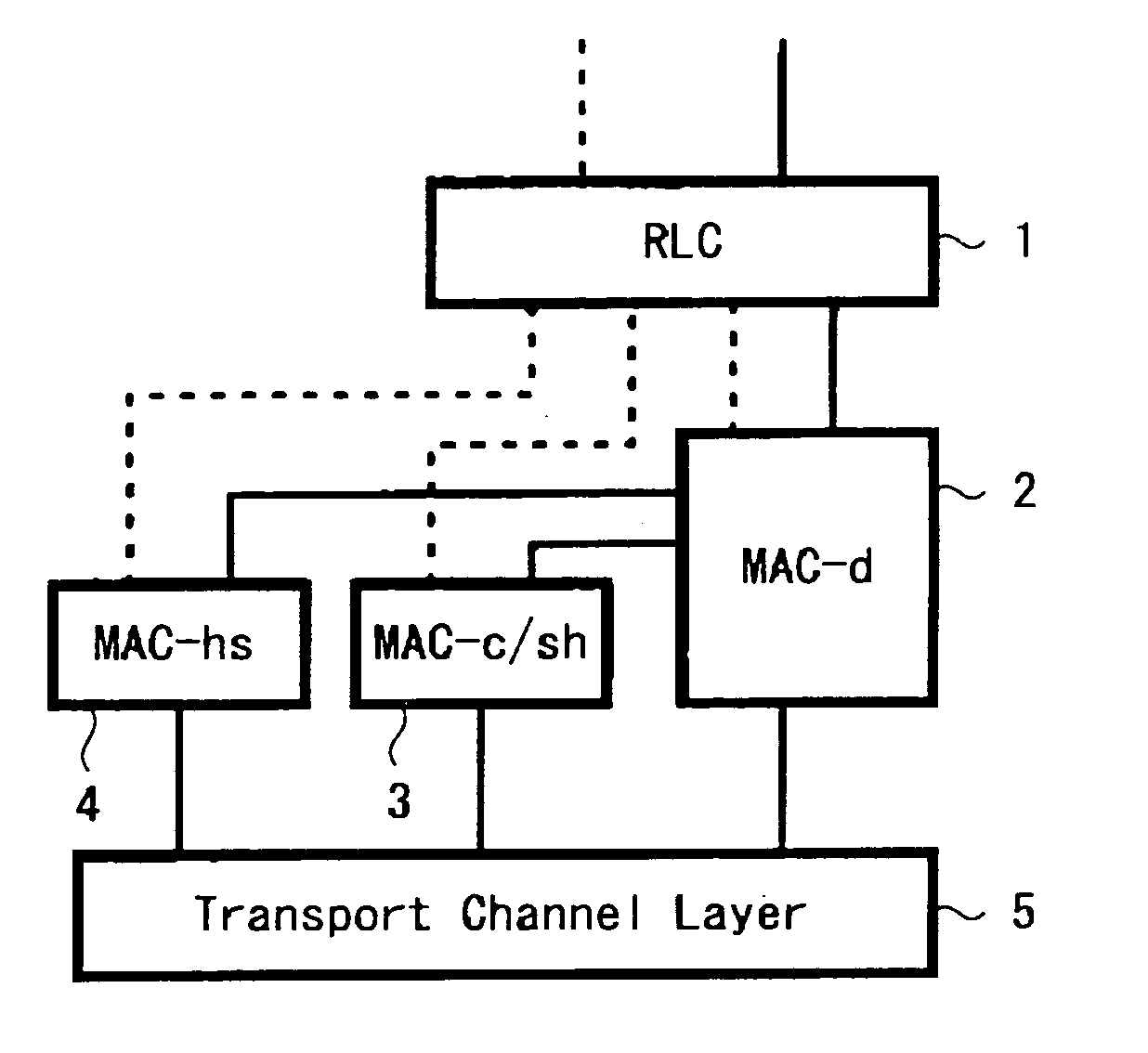
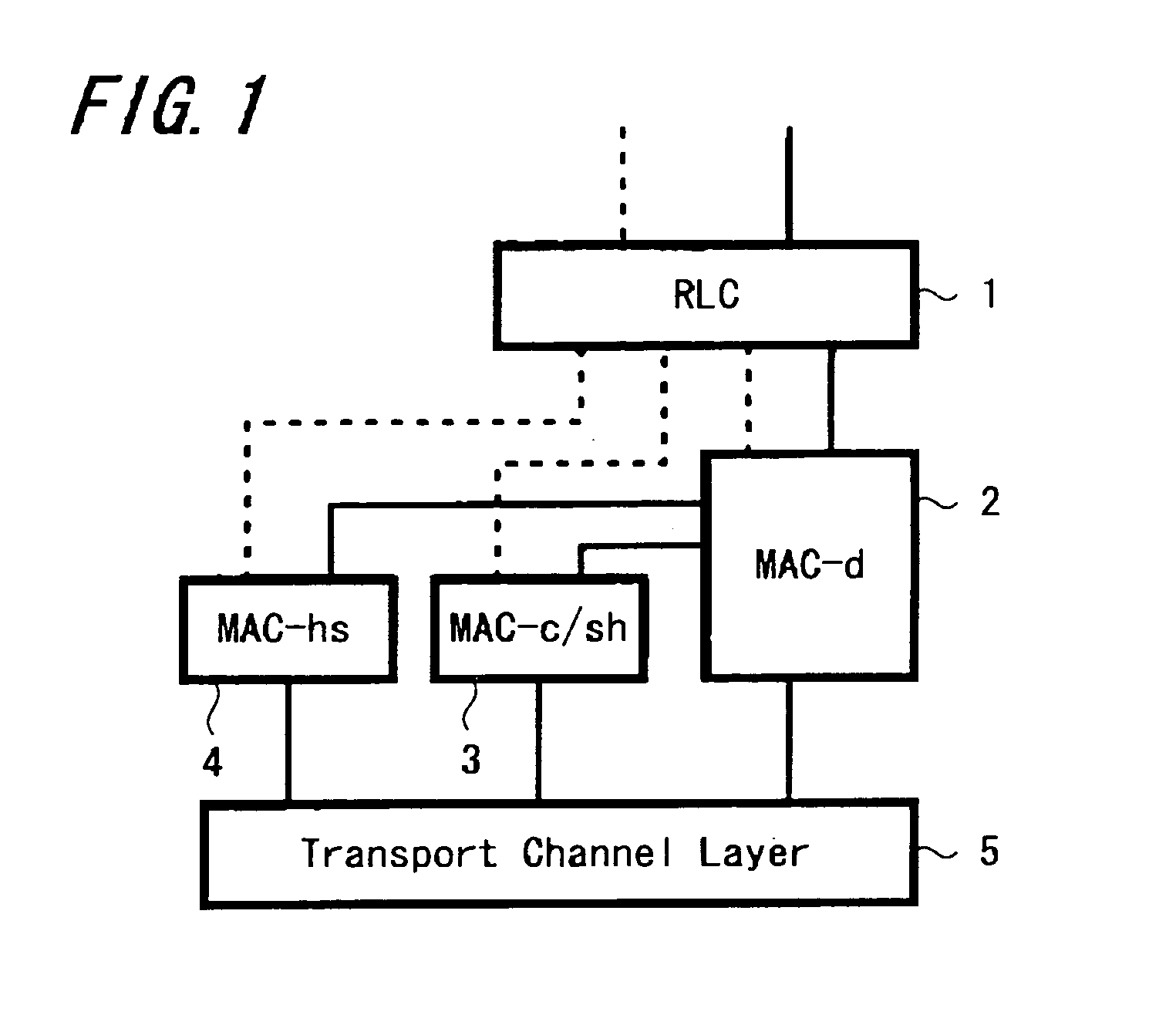
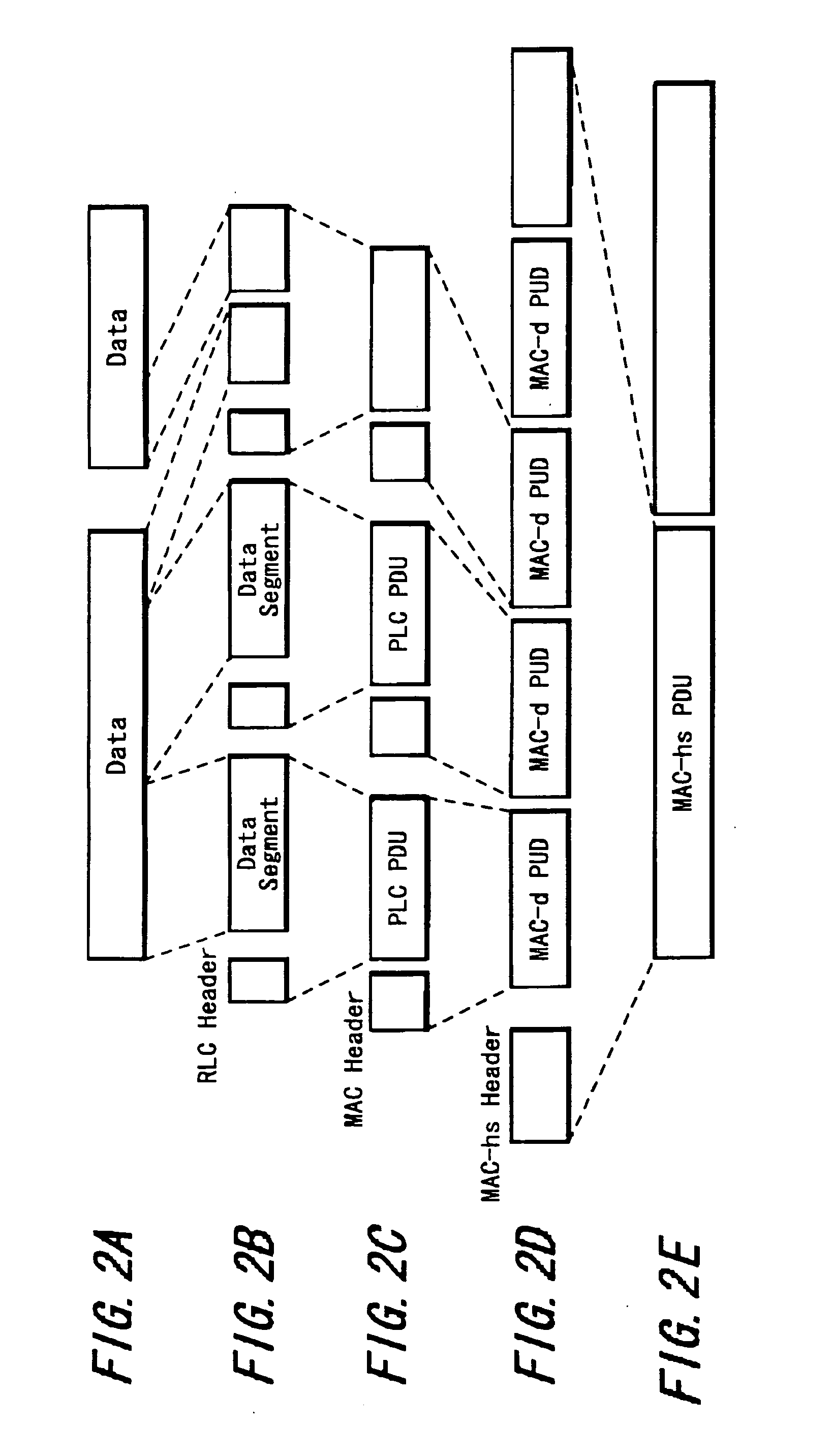
[0046] HSDPA methods have already been explained in the description of related art, and therefore an explanation is not here repeated. The layer structure shown in FIG. 1 is employed, with a MAC-d layer 2, MAC-c layer 3, and MAC-hs layer 4 existing below the RLC (Radio Link Control) layer 1, and with a transport channel layer 5 existing below the MAC layers 2, 3 and 4, to perform transmission and reception using a physical communication channel. With respect to the protocol data units (PDUs) of each of the layers, the configuration of FIG. 2, previously explained, is also employed.

[0047] The HSDPA method is employed in a system in which high-speed downlink data transmission is performed from a wireless telephone system base station to mobile ph...


PUM


Abstract

When retransmission requests are issued based on the results of error-correction decoding of received data packets to perform data transmission, statistical information indicating whether received data packets have been successfully decoded or have not been decoded is acquired, and based on the rate at which correct decoding has been made or the rate at which correct decoding has not been made, which is obtained from the statistical information, a request is transmitted to the transmission source to change the window size, which is the number of data units handled in a predetermined layer, so that when for example the communication environment is not excellent, processing can be performed at a small window size, and the occurrence of circumstances in which data retransmission and the discarding of received data are repeated can be efficiently prevented. Accordingly, data transmission efficiency in a wireless transmission system performing high-speed data transmission is improved under conditions of a poor radio wave environment.

Description

BACKGROUND OF THE INVENTION [0001] 1. Field of the Invention [0002] This invention relates to a transmission method and a transmission apparatus suitable for application to wireless transmission processing in which retransmission control is performed. [0003] 2. Description of the Related Art [0004] Channel encoding (error-correction encoding) and automatic repeat request (ARQ) are known as methods of error control in wireless transmission applied to wireless telephone communication and other systems. In packet transmission, error-free transmission is necessary, so that error control must be performed using ARQ. Further, when applying adaptive modulation / demodulation and error correction to select the optimum modulation method and encoding method according to the propagation path conditions in order to improve throughput, packet errors arising due to measurement errors, control delays and other causes are unavoidable; hence as described in non-patent reference 1, a technology called ...

Claims


Application Information

Patent Timeline
IPC IPC(8): H04B7/26H04L1/16H04L1/18H04L47/27H04L47/36H04L47/43H04W28/04H04W28/06
CPCH04L1/0019H04L1/1607H04L1/188H04L1/1838H04L1/187H04L1/1812H04N21/26258H04N21/45
Inventor YAMAMOTO, KATSUYA
Owner SNAPTRACK
Why Eureka
Try Eureka