Machine for automatically cutting PIN feet
An automatic and pneumatic lifting technology, applied in the direction of shearing machine equipment, shearing devices, metal processing equipment, etc., can solve the problems of slow operation speed, short service life, low production efficiency, etc., to improve utilization rate, reduce scrap rate, The effect of improving productivity
- Summary
- Abstract
- Description
- Claims
- Application Information
AI Technical Summary
Problems solved by technology
Method used
Image

Examples
Embodiment Construction
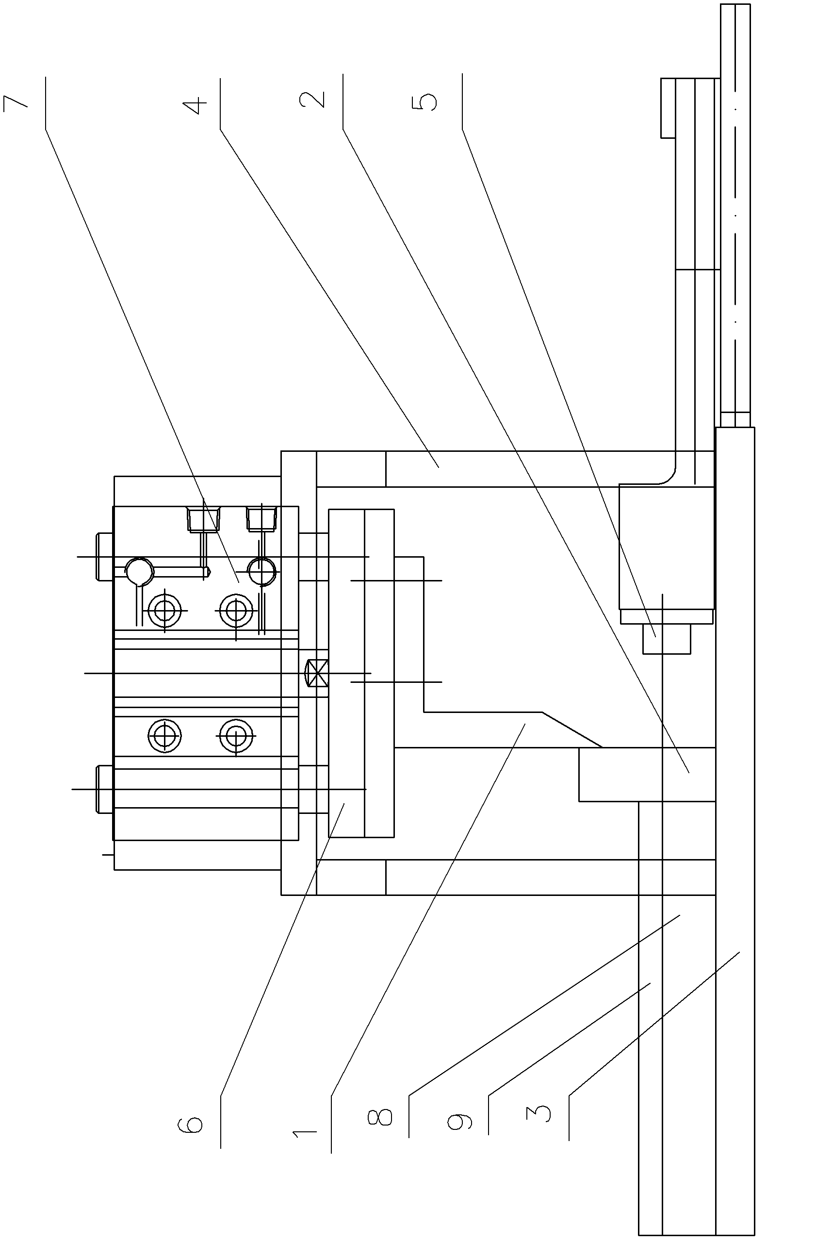
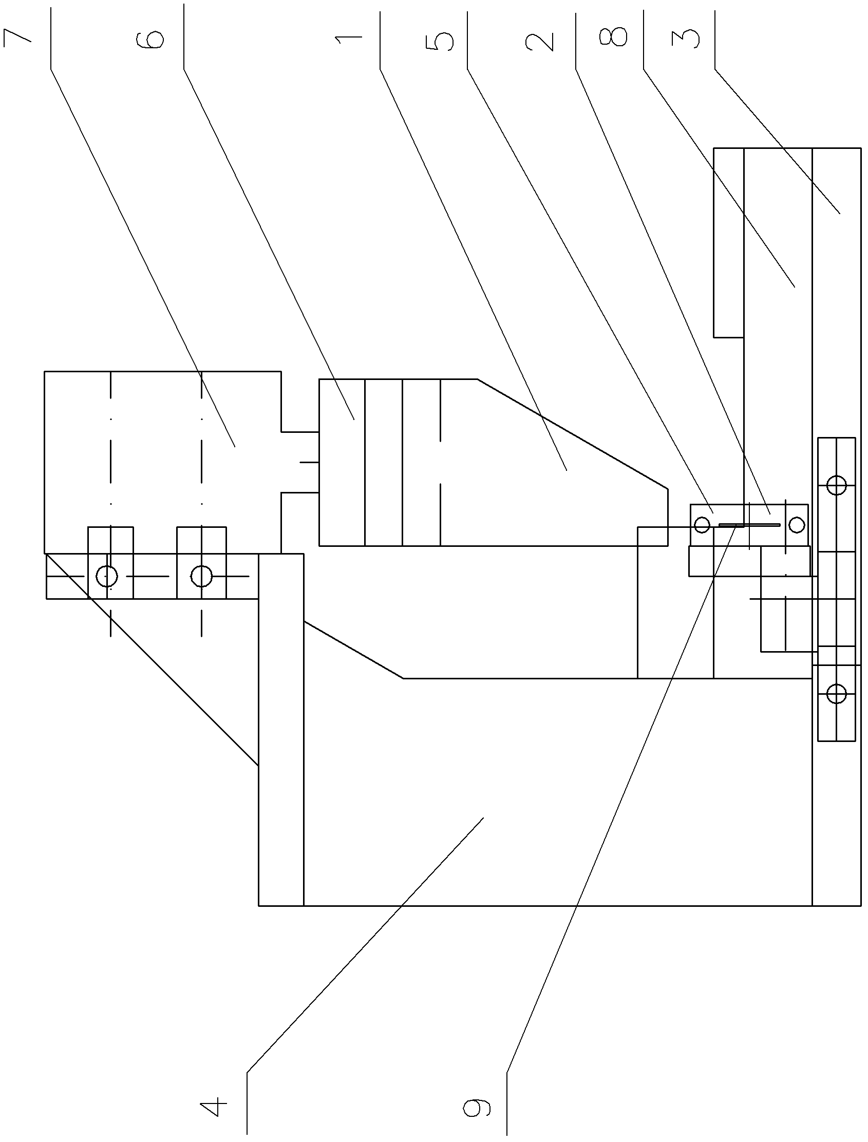
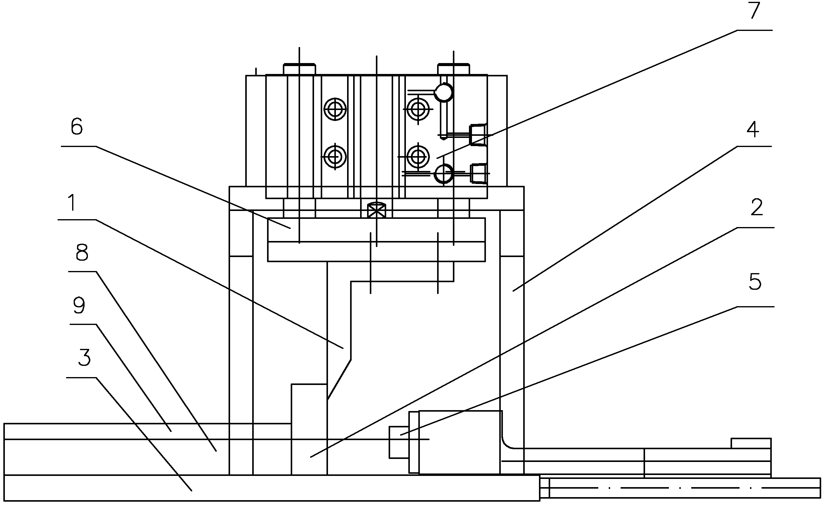
[0020] The automatic pin cutting machine of the present invention is mainly composed of a moving knife 1, a fixed knife 2, a bottom plate 3, a positioning block 5, a moving knife lifting mechanism and a PIN foot counter. The fixed knife 2 is longitudinally installed on the bottom plate 3, and the left side of the fixed knife 2 is arranged Pad the spacer 8 of the fixed knife 2, the vertical guide plate 9 is arranged on the spacer 8, the spacer 8 and the guide plate 9 form a feeding groove connecting the fixed knife 2 at right angles, the bottom plate 3 on the right side of the fixed knife 2 is installed through the adjustment device Positioning block 5, the end of positioning block 5 is higher than feeding groove, and positioning block 5 is adjustable along the position of feeding direction, as figure 1 , figure 2 shown.
[0021] The main body of the moving knife lifting mechanism is a cylinder 7, and the cylinder 7 is fixedly installed above the base plate 3 through the brac...
PUM
 Abstract
Description
Claims
Application Information
 - Generate Ideas
- Intellectual Property
- Life Sciences
- Materials
- Tech Scout
- Unparalleled Data Quality
- Higher Quality Content
- 60% Fewer Hallucinations
Browse by: Latest US Patents, China's latest patents, Technical Efficacy Thesaurus, Application Domain, Technology Topic, Popular Technical Reports.
© 2025 PatSnap. All rights reserved.Legal|Privacy policy|Modern Slavery Act Transparency Statement|Sitemap|About US| Contact US: help@patsnap.com