Power tool

A technology of power tools and transmission parts, applied in the field of power tools, can solve the problems of complex structure, easy occurrence of danger, inconvenient use, etc.

Inactive Publication Date: 2011-10-19
POSITEC POWER TOOLS (SUZHOU) CO LTD
View PDF2 Cites 7 Cited by
  • Summary
  • Abstract
  • Description
  • Claims
  • Application Information

AI Technical Summary

Problems solved by technology

In the electric circular saw disclosed in US Patent No. 5,430,944, a disc with a groove is fixed on the output shaft of the motor, and a piston and a pressing rod are arranged on the casing, and the pressing rod is operated so that the piston enters the groove of the disc to thereby Lock the output shaft, release the pressure rod, the piston resets under the elastic force of the compression spring to release the output shaft, but this kind of shaft locking device has many parts and complex structure, and it needs one hand to operate the pressure rod to lock the output shaft, and the other hand to lock the output shaft. Use tools such as wrenches to disassemble and assemble the working head, which is laborious and inconvenient to use
German patent DE19938299A1 discloses that the shaft locking device of an electric circular saw is arranged in the shaft center hole of the output shaft. When a wrench is inserted to disassemble the working head, the wrench pushes the shaft locking device to move axially against the motor fan to lock the output shaft. , when the wrench is taken out, the shaft locking device resets and loosens the output shaft under the action of the elastic element. This shaft locking device uses the wrench to lock the output shaft while disassembling the working head, which is prone to danger, especially if the operator forgets to When the wrench is removed and the motor is started, the wrench may fly out at high speed causing an accident, or the output shaft is still locked causing damage to the motor

Method used


Image

  • Power tool
  • Power tool
  • Power tool

Examples


Embodiment Construction

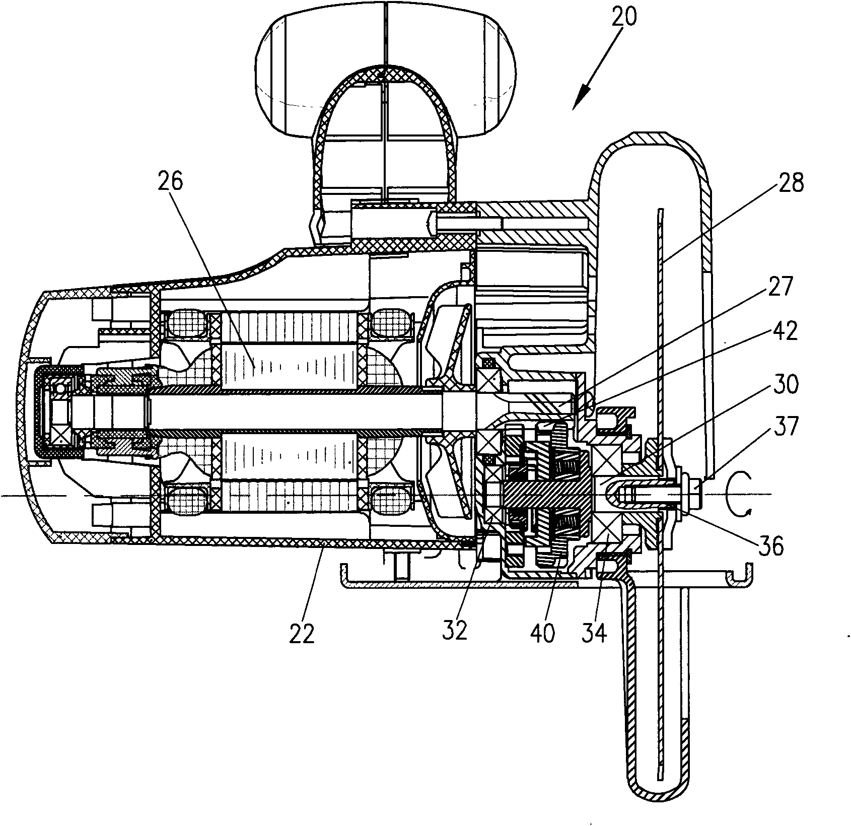
[0051] The present invention takes an electric circular saw as a preferred embodiment to specifically illustrate the shaft locking structure of a power tool.

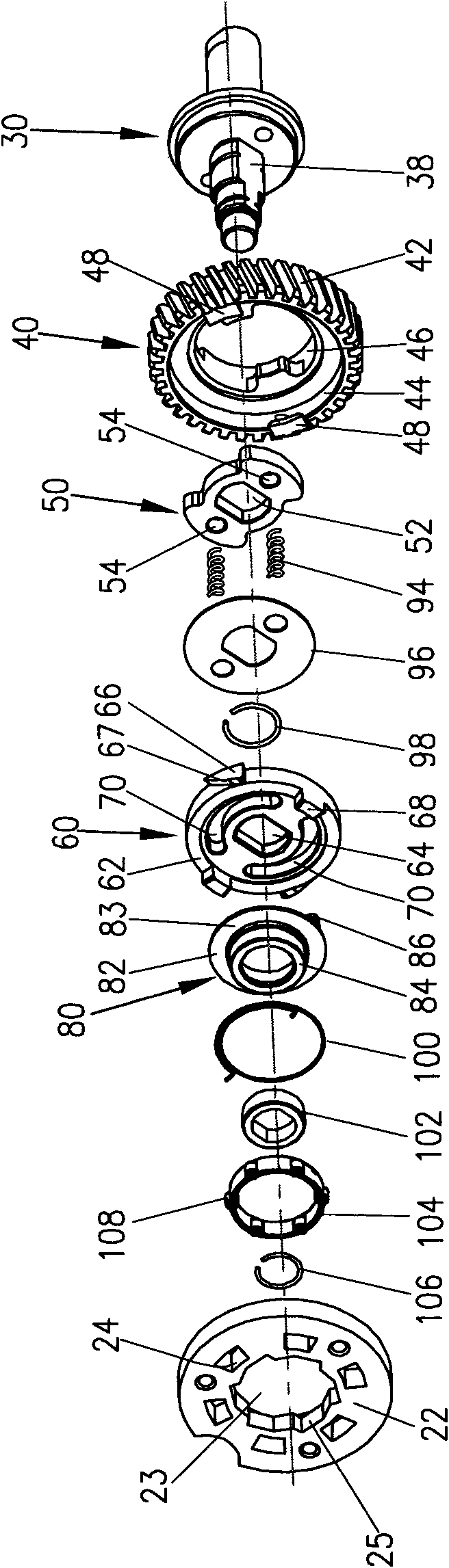
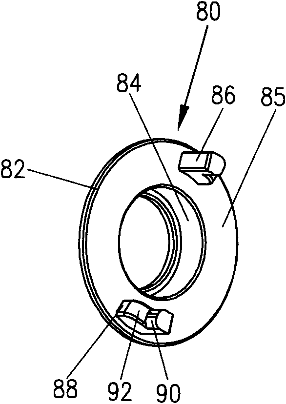
[0052] refer to figure 1As shown, the electric circular saw 20 in the first preferred embodiment of the present invention includes a casing 22, a motor 26 with a motor shaft 27 accommodated in the casing 22, an output shaft 30 connected to the saw blade 28, and the output shaft 30 The bearings 32, 34 are rotatably installed on the casing 22, and one end of the output shaft 30 is provided with a threaded hole 36 to be threadedly connected with the fastener 37 fixing the saw blade 28, and the other end is sleeved with a gear 40, and the outer end of the gear 40 The ring gear 42 meshes with the motor shaft 27 to transmit the rotational motion of the motor 26 to the output shaft 30 . In order to prevent the output shaft 30 from co-rotating when using tools such as a wrench to rotate the fastener 37 to disassemble the saw b...


PUM


Abstract

The invention discloses a power tool, comprising an enclosure, a motor held in the enclosure, an output shaft adapted with a working head, at least one transmission member driven to rotate by the motor and a locking device being arranged on the output shaft and being capable of moving between a locking position for stopping the rotation of the output shaft and a loosing position for allowing the rotation of the output shaft. The transmission member is movably adapted with the output shaft, and therefore, the motor drives the locking device to move from the locking position to the loosing position along the radial direction of the output shaft during starting. The locking device on the output shaft of the power tool can be automatically unlocked when the motor is started up.

Description

[0001] This application is a divisional application of the Chinese invention patent application filed by the applicant on December 21, 2006. technical field [0002] The invention relates to a power tool, especially a disc-shaped working head with a large inertia, which needs to lock the output shaft when the working head is replaced, such as electric circular saw, angle grinder, sander, miter saw and large cutting machines etc. Background technique [0003] Power tools such as electric circular saws, angle grinders, sanders, miter saws, and large cutting machines are usually driven by a motor to rotate the output shaft to drive the working head to rotate for cutting, grinding, etc., but in the long-term use of the working head It is easy to wear and need to replace the working head, and it is often necessary to replace the working head of various specifications during the operation, but when the working head is disassembled with a wrench or a tool with similar functions, th...

Claims


Application Information

Patent Timeline
Patent Type & Authority Applications(China)
IPC IPC(8): B25F5/00
Inventor 陈成忠
Owner POSITEC POWER TOOLS (SUZHOU) CO LTD
Why Eureka
Try Eureka