Electronic control unit

一种电控单元、地电的技术,应用在电气元件、泵控制、液体变容式机械等方向,能够解决输出端子短路、进水等问题,达到降低端子断路的风险的效果

Active Publication Date: 2011-10-19
THE GATES CORP
View PDF7 Cites 9 Cited by
  • Summary
  • Abstract
  • Description
  • Claims
  • Application Information

AI Technical Summary

Problems solved by technology

The disadvantage of this connection method is that there is a risk of water entering the connection between the output terminal and the stranded wire, causing a short circuit at the output terminal

Method used


Image

  • Electronic control unit
  • Electronic control unit
  • Electronic control unit

Examples


Embodiment Construction

[0022] The technical solutions and other beneficial effects of the present invention will be apparent through the detailed description of specific embodiments of the present invention below in conjunction with the accompanying drawings.

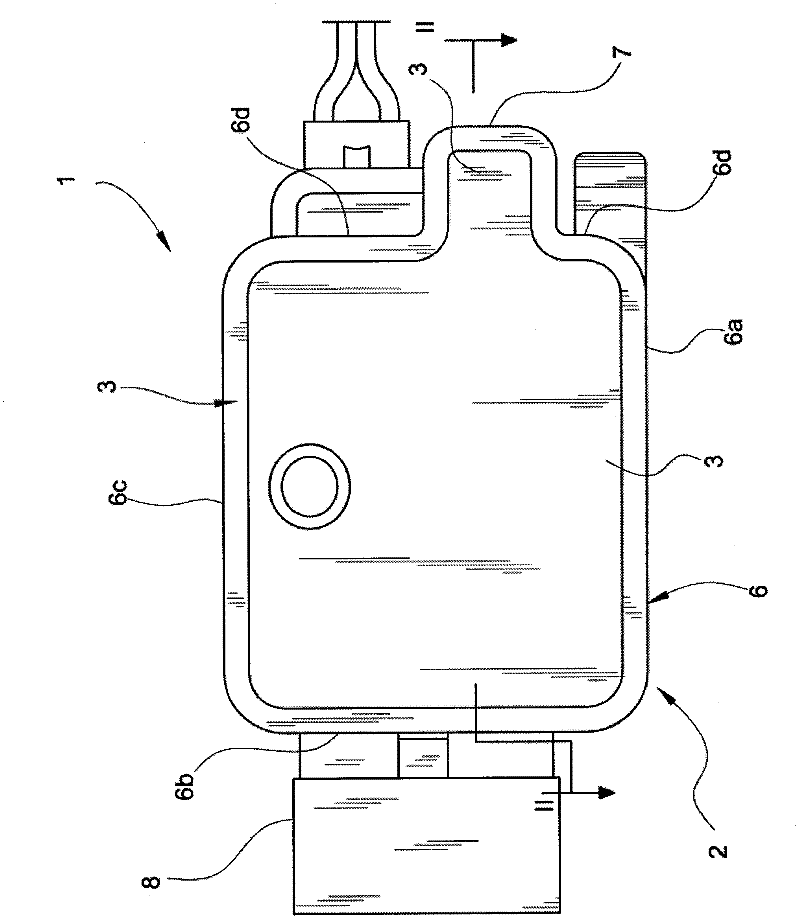
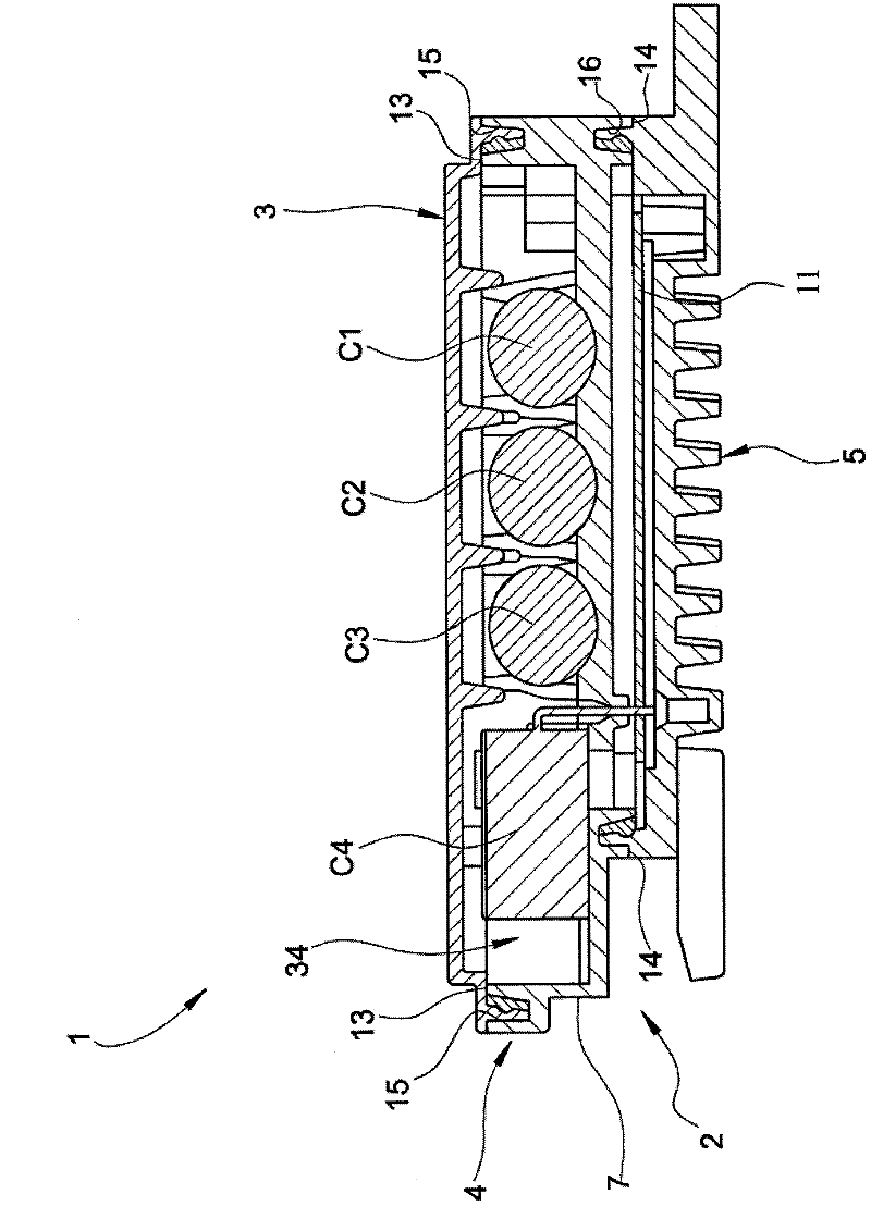
[0023] refer to figure 1 and figure 2 , The electronic control unit 1 provided by an example of the present invention includes a device for adjusting or controlling the rotation speed of an electric fan, especially a car electric fan. However, the present invention is not limited to this specific field.

[0024] The electronic control unit 1 includes a housing 2, the housing 2 includes a top cover 3 made of plastic, an intermediate member 4 made of plastic and a radiator 5 made of metal, the plastic can be PBT (polyethylene terephthalate) ester), the metal can be aluminum or aluminum alloy. In this example, the radiator 5 serves as the bottom cover of the housing 2 .

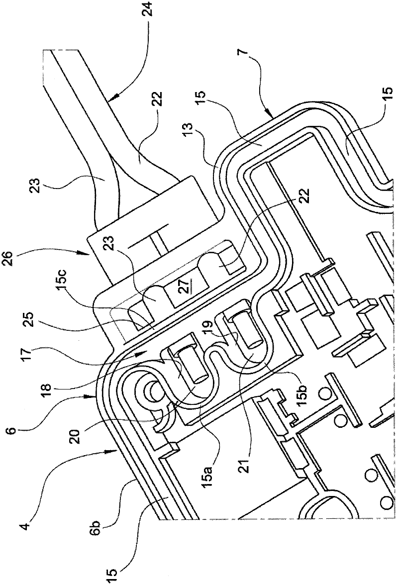
[0025] like image 3 and Figure 5 As shown, the intermediate membe...


PUM


Abstract

An electronic control unit comprises: an injection-molded supporting structure (4) for forming a cavity therein; a circuit board (11) mounted on the supporting structure; at least two electrically conductive members (20,21) combined with the supporting structure (4) during molding the supporting structure (4), wherein one end of the electrically conductive member is connected with the circuit board (11) and another end extends into the cavity (17); at least two flexible conductors (22,23), each flexible conductor comprising a corresponding insulation outer layer, wherein the flexible conductors (22,23) are combined with the supporting structure (4) when molding the supporting structure (4) and the ends of the flexible conductor (22,23) extend into the cavity (17) and permanently electrically connected with the conductive members (20,21) and the connection position of the flexible conductors (22,23) and the conductive members (20,21) is covered and sealed by a water-proof insulation material. The water intake risk of the electronic control unit is reduced and the member short circuit is prevented.

Description

technical field [0001] The invention relates to an electric control unit, which can be used as a speed regulator of an electric fan. Background technique [0002] US Patent No. 7,085,138 discloses an electronic control unit, which includes a circuit board installed with electronic components, a support structure for mounting the circuit board, and multi-strand wires for connecting the electronic control unit and controlled equipment. The support structure is made of plastic, and at least two conductive terminals are partially bonded to the shell of the support structure during the injection molding process of the support structure, the two conductive terminals are connected to the circuit board and serve as output terminals of the electronic control unit. The multi-strand wire includes at least one pair of flexible conductors, each flexible conductor has a corresponding insulating outer layer, one end of the flexible conductor is connected to the above-mentioned output termi...

Claims


Application Information

Patent Timeline
Patent Type & Authority Applications(China)
IPC IPC(8): F04B49/06
CPCH02G3/088H02G3/16F04B49/007
Inventor 马克·布萨吉欧凡尼·迪萨特
Owner THE GATES CORP
Why Eureka
Try Eureka