Non-contact vehicle gear sensor

A kind of automobile gear position and non-contact technology, which is applied in the field of sensors, can solve the problems of easy failure, poor contact, easy wear, etc., and achieve the effect of accurate and stable output signal, prolonging working life, improving reliability and safety

Inactive Publication Date: 2011-10-19
HEFEI BANGLI ELECTRONICS
View PDF0 Cites 6 Cited by
  • Summary
  • Abstract
  • Description
  • Claims
  • Application Information

AI Technical Summary

Problems solved by technology

[0005] In order to solve the problem of poor contact and easy failure caused by the easy wear of the existing contact gear sensor, the present invention provides a non-contact automotive gear sensor

Method used


Image

  • Non-contact vehicle gear sensor
  • Non-contact vehicle gear sensor
  • Non-contact vehicle gear sensor

Examples


Embodiment

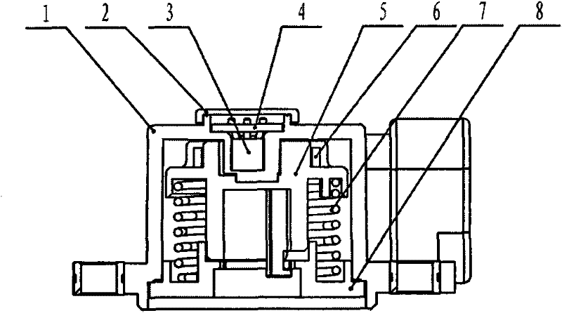
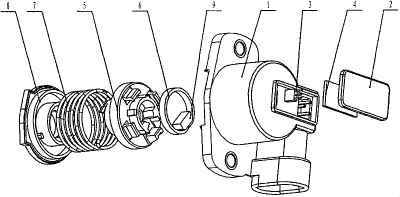
[0021] see figure 1 and figure 2 , the non-contact automobile gear position sensor includes a cylindrical casing 1, an upper cover plate 2 is arranged at the axial top of the casing 1, and a lower cover plate 8 is arranged at the axial bottom; the inner side of the upper cover plate 2 is provided with a circuit board 4. The circuit board 4 is connected to the Hall chip 3, the Hall chip 3 is located in the housing 1, the outer side of the Hall chip 3 is provided with a hollow rotating shaft 5, and the upper part of the hollow rotating shaft 5 corresponding to the Hall chip 3 is sleeved. The magnetic conducting ring 6, the inner side wall of the magnetic conducting ring 6 is connected with the magnet 9, and the magnet 9 corresponds to the Hall chip 3; the outer middle of the hollow shaft 5 is radially provided with a positioning ring, and the upper surface of the positioning ring is evenly provided with three hooks , the hook catches the magnetic conductive ring 6 sleeved on t...


PUM


Abstract

The invention relates to a non-contact vehicle gear sensor, wherein the axial top part of a shell of the non-contact vehicle gear sensor is equipped with an upper cover plate while the axial bottom part of the shell of the non-contact vehicle gear sensor is provided with a lower cover plate; a circuit board is arranged on the inner side of the upper cover plate; a hall chip is connected to the circuit board; the hall chip is located in the shell; the outer side of the hall chip is equipped with a hollow rotating shaft; a magnetic conducting ring is sleeved on the upper part of the hollow rotating shaft, corresponding to the hall chip; one side wall in the magnetic conducting ring is connected with a magnet; the magnet corresponds to the hall chip; a locating ring is radially arranged on the middle part of the outer side of the hollow rotating shaft; a return spring is sleeved on the hollow rotating shaft on the lower part of the locating ring; and the upper end and the lower end of the return spring are located on the locating ring and the lower cover plate. According to the non-contact vehicle gear sensor disclosed by the invention, the contact abrasion problem is solved; the service life of the sensor is largely prolonged; and the working reliability and the safety are improved.

Description

technical field [0001] The invention belongs to the technical field of sensors, and in particular relates to a vehicle gear position sensor. Background technique [0002] The electric mechanical automatic transmission (AMT) is based on the conventional manual transmission, with an additional set of electronic control devices, which can automatically control the clutch and shift lever of the manual transmission, so that the disengagement and engagement of the clutch are automatic. of. AMT gearboxes combine the advantages of high transmission efficiency of mechanical gearboxes and convenient operation of automatic gearboxes, and are widely used in various types of vehicles. [0003] The AMT gearbox realizes the shifting and swinging shifting of the shifting fork shaft of the gearbox and the engagement of the clutch by controlling the rotation angle of the motor. The gear position sensor is the most important measurement and control link in the AMT transmission system. The ac...

Claims


Application Information

Patent Timeline
Patent Type & Authority Applications(China)
IPC IPC(8): F16H63/42
Inventor 张肖康周守元周革
Owner HEFEI BANGLI ELECTRONICS
Why Eureka
Try Eureka