Rubber-tired container gantry crane and steering device thereof

A technology for gantry cranes and steering devices, which is applied to traveling bridge cranes, cranes, traveling mechanisms, etc., can solve problems such as high maintenance costs and complicated steering devices, and achieve the effects of convenient operation, compact structure, and light weight

Inactive Publication Date: 2011-11-02
SANY MARINE HEAVY IND
6 Cites 9 Cited by

AI-Extracted Technical Summary

Problems solved by technology

The steering device is more complicat...

Method used

In summary, in the tire-type container gantry crane of the present invention and its steering device, the two ends of the push rod 5 that can be output by both heads are pushed and pulled in the same direction, and one end is "pushed" to realize the vehicle connected to it. The other end realizes the steering of the frame connected to it by "pulling", so that the left support frame 3 and the right support frame 9 can rotate in the same direction, and the push-pull action of the two frames only relies on one linear movement It can be completed, and there is no need to arrange connecting rods on the other side of the cart balance beam 1 to connect the two frames, which has the advantages of less parts, light weight, and compact structure. In addition, by controlling the position of the push rod 5 capable of double output, the functions of positioning and locking can be realized, the operation is very convenient, and it is a simple, economical and safe steering device.
Shown in Fig. 3 is the structural diagram of the mechanical push rod 5 of an embodiment of the present invention, and this mechanical push rod 5 comprise...

Abstract

The invention provides a rubber-tired container gantry crane and a steering device thereof. The steering device is characterized in that the device comprises a cart equalizer bar, a left supporting cart frame, a right supporting cart frame, pivoting supports and a push rod which can move in two directions; left wheels are arranged below the left supporting cart frame; right wheels are arranged below the right supporting cart frame; the left supporting cart frame is provided with an area allowing a pin roll connection; the left supporting cart frame and the right supporting cart frame are connected to the cart equalizer bar through the pivoting supports; one end of the push rod is connected to a pin roll of the left supporting cart frame and the other end of the push rod is connected to a pin roll of the right supporting cart frame; and the two ends of the push rod move in the same direction to drive the left supporting cart frame and the right supporting cart frame to rotate in the same direction. The steering device realizes a direction change without a lifting-up structure, does not need a connecting rod and its associated parts, has the advantages of less parts, light quality and compact structure.

Application Domain

Technology Topic

Image

  • Rubber-tired container gantry crane and steering device thereof
  • Rubber-tired container gantry crane and steering device thereof
  • Rubber-tired container gantry crane and steering device thereof

Examples

  • Experimental program(1)

Example Embodiment

[0028] The technical solutions in the embodiments of the present invention will be clearly and completely described below in conjunction with the accompanying drawings in the embodiments of the present invention. Obviously, the described embodiments are only a part of the embodiments of the present invention, rather than all the embodiments. Based on the embodiments of the present invention, all other embodiments obtained by those of ordinary skill in the art without creative work shall fall within the protection scope of the present invention.
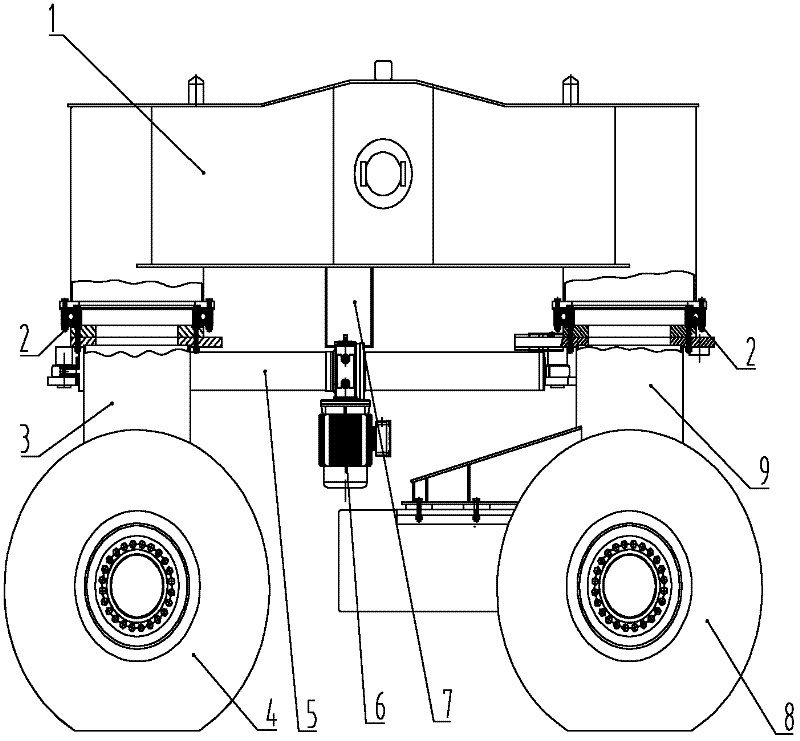
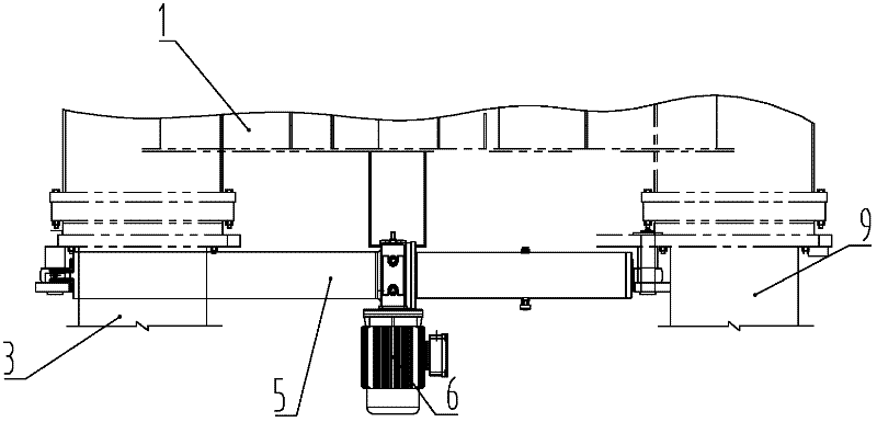
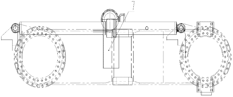
[0029] figure 1 Shown is the overall structure diagram of the steering device of a tire-type container gantry crane according to an embodiment of the present invention. It can be seen from the figure that the steering device of the tire-type container gantry crane of the present invention at least includes a trolley balance beam 1, a left supporting frame 3 and a right supporting frame 9, a slewing support 2 and a double-headed push rod 5 . The trolley balance beam 1 is used to ensure the balance of each wheel, and its structure refers to the prior art, which will not be repeated here.
[0030] A left wheel 4 is provided under the left support frame 3, and a right wheel 8 is provided under the right support frame 9. Both the left support frame 3 and the right support frame 9 are provided with pin shaft connection areas. The pin connection area can be either a pin hole or a pin fixed to the frame, as long as the left support frame 3 and the right support frame 9 can be connected to the push rod 5 capable of double-headed output. The pin shaft connection can realize the technical effect of the present invention, and the present invention is not limited to this. The pinable connection area can be located at multiple positions on the left support frame 3 and the right support frame 9, preferably on the same side of the left support frame 3 and the right support frame 9, so as to facilitate the two frames Turn in the same direction at the same time. More preferably, both the left supporting frame 3 and the right supporting frame 9 are provided with a pinable connection area at the same position on the left side. The left support frame 3 and the right support frame 9 are connected to the trolley balance beam 1 through the slewing support 2, and the overall steering of the tire-type container gantry crane can be realized through the rotation of the slewing support.
[0031] One end of the push rod 5 capable of double-head output is connected with the left support frame 3 and the other end is connected with the right support frame 9 with pins. Both ends of the push rod 5 move in the same direction. The left support frame 3 and the right support frame 9 are driven to rotate in the same direction. In the working process of the tire-type container gantry crane steering device of the present invention, the two ends of the push rod 5 that can be outputted by two ends move in the same direction relative to the stationary part (such as the left wheel 4 and the right wheel 8), such as simultaneously Move straight to the left. Those skilled in the art can use a variety of mechanical, electric or hydraulic methods to achieve the double-headed output of the push rod 5. Preferably, the output length of the push rod 5 capable of double-headed output can make the left supporting frame 3 and the right supporting frame 9 rotate in the same direction by 60-120°, more preferably 90°.
[0032] As a preferred embodiment, the push rod 5 capable of double-headed output is a hydraulic push rod. The hydraulic push rod uses a steering drive power source 6 such as a hydraulic pump to provide power to drive the two ends of the push rod to move. Preferably, the steering drive power source 6 is connected as a whole through the support of the push rod 5. After adopting the above structure, the steering device of the tire-type container gantry crane of the present invention can make the left support frame 3 and the right support frame connected with the pins of the two ends of the hydraulic push rod 5 under the double-head output of the hydraulic push rod 5 The frame 9 rotates in the same direction, thereby realizing the overall steering of the tire-type container gantry crane. This structure does not require a connecting rod to be arranged on the other side of the trolley balance beam 1 to connect the two frames, nor does it require a jacking mechanism to achieve steering.
[0033] As another preferred embodiment, the push rod 5 capable of double-headed output of the present invention is a mechanical push rod. Its arrangement in the steering device of the rubber-tyred container gantry crane is as follows Figure 2a-2b Shown. Such as Figure 2a As shown, the push rod 5 capable of double-head output is driven by a steering drive power source 6 such as an electric motor. The steering drive power source 6 can be arranged at multiple positions in the tire-type container gantry crane, preferably a linear slide 7 is provided under the balance beam, and the steering drive power source 6 is installed in the linear slide 7 . The linear slide 7 is perpendicular to the connecting direction of the left support frame 3 and the right support frame 9. When the tire-type container gantry crane of the present invention turns, the steering drive power source 6 moves linearly in the slide 7 . In addition, the steering drive power source 6 can also be connected as a whole through the support of the push rod 5. In addition, in Figure 2b It can also be seen that both the left supporting frame 3 and the right supporting frame 9 are provided with a pinable connection area at the same position on the left side, and the pinable connection area can also be set at other positions. The present invention does not Limited by this.
[0034] image 3 Shown is a structural diagram of a mechanical push rod 5 according to an embodiment of the present invention. The mechanical push rod 5 includes a trapezoidal screw pair and a worm gear pair (not shown) that are connected to each other. The worm gear pair and the steering drive The power source 6 is connected. The trapezoidal screw rod pair includes a nut 51 and a screw rod 52. The threads of the nut 51 and the screw rod 52 have a trapezoidal structure to withstand a greater torque when the tire-type container gantry crane of the present invention turns. The rotation of the worm gear and the nut 51 can be realized by the steering drive power source 6 to drive the worm gear pair and the rotation of the nut 51. At this time, the steering drive power source 6 slides in the linear slide 7 under the balance beam. in image 3 In the illustrated embodiment, both ends of the mechanical push rod 5 are respectively provided with pin holes 53 and 54 to form a pin connection with the left support frame 3 and the right support frame 9 respectively. In addition, it is also possible to fix pin shafts at both ends of the mechanical push rod 5 respectively, and it is also possible to realize the pin shaft connection with the frame, and the present invention is not limited to this.
[0035] In the working process of the tire-type container gantry crane steering device of the present invention, if the steering drive power source 6 drives the push rod 5 to move linearly to the left, since the push rod 5 is a double-headed output, its left end is "pushed" by a pin. The connected left supporting frame 3 rotates, and the right end of the connected right supporting frame 9 rotates through the pin "pull", which can realize the synchronous steering of the left and right frames; if the steering drive power source 6 drives the push rod 5 straight to the right Move, its left end is "pulled" through the pin to rotate the connected left support frame 3, and the right end is "push" through the pin to move the connected right support frame 9 to rotate, so that the left and right frames can turn in the other direction simultaneously. . When the push rod 5 is stationary and does not move, the positioning and locking functions of the tire-type container gantry crane can be realized.
[0036] In addition to the above-mentioned steering device, the present invention also provides a tire-type container gantry crane including the above-mentioned steering device. The structure of other parts of the tire-type container gantry crane refers to the prior art, and will not be repeated here.
[0037] In summary, the tire-type container gantry crane and its steering device of the present invention can push and pull both ends of the double-headed push rod 5 in the same direction, and one end of the push rod 5 is "pushed" to realize the steering of the frame connected to it. , The other end is "pull" to realize the steering of the frame connected to it, which can realize the left support frame 3 and the right support frame 9 to rotate in the same direction. The push and pull action of the two frames can be completed by only one linear movement , There is no need to arrange a connecting rod on the other side of the trolley balance beam 1 to connect the two frame, which has the advantages of fewer parts, light weight, compact structure and the like. In addition, by controlling the position of the push rod 5 capable of double-head output, the positioning and locking functions can be realized, and the operation is very convenient, and it is a simple, economical and safe steering device.
[0038] Therefore, the beneficial effects of the present invention are obvious.
[0039] The above descriptions are only preferred embodiments of the present invention and are not intended to limit the present invention. Any modification, equivalent replacement, improvement, etc. made within the spirit and principle of the present invention shall be included in the present invention. Within the scope of protection.

PUM

no PUM

Description & Claims & Application Information

We can also present the details of the Description, Claims and Application information to help users get a comprehensive understanding of the technical details of the patent, such as background art, summary of invention, brief description of drawings, description of embodiments, and other original content. On the other hand, users can also determine the specific scope of protection of the technology through the list of claims; as well as understand the changes in the life cycle of the technology with the presentation of the patent timeline. Login to view more.

Similar technology patents

Modularized biomimetic robotic dolphin push mechanism

InactiveCN102730176ASimple structureFew partsPropulsive elements of non-rotary typeEngineeringGravitation
Owner:北京中科融盛海洋科技有限公司

Lubricating method and lubricating structure of four-stroke gasoline engine

InactiveCN101749074ASimple stepsFew partsMachines/enginesClosed-circuit pressure lubricating systemsPistonOil can
Owner:昆山兴宝塑料制品有限公司

Classification and recommendation of technical efficacy words

  • Light in mass
  • Few parts
Why Eureka
Try Eureka