Airflow fabric finishing machine

A post-finishing, air-flow technology, applied in the direction of fabric surface trimming, textile and papermaking, roughening, etc., can solve the problems affecting the quality of fabric finishing, affecting the effect of fabric finishing, etc., to achieve the effect of protecting the environment

Active Publication Date: 2011-11-02
苏州博杰思达机械有限公司
View PDF11 Cites 3 Cited by
  • Summary
  • Abstract
  • Description
  • Claims
  • Application Information

AI Technical Summary

Problems solved by technology

However, there are still the following shortcomings: the temperature of the dust-laden air drawn from the dust removal air duct is still high, and it will be discharged without recycling, which will damage the environment and waste energy
[0005]The reason why the industry does not use the dust-laden hot air drawn from the dust-removing air duct is based on the following two factors: First, due to The waste hot air drawn from the dust removal duct contains a large amount of fluff and dust from the fabric. Therefore, if this air is returned to the air heating mechanism for heating, energy can be saved, but the fluff and dust will cause damage to the fabric in the process. If we weigh the pros and cons, it is obvious that the gains outweigh the losses. The so-called gains are energy saving, and the so-called losses are serious effects on the finishing quality of fabrics; The humidity is higher than that of the outside air, so if it is reused, it will seriously affect the finishing effect of the fabric, and it will also produce counterproductive results

Method used


Image

  • Airflow fabric finishing machine
  • Airflow fabric finishing machine
  • Airflow fabric finishing machine

Examples


Embodiment Construction

[0021] In order to enable the examiners of the patent office, especially the public, to understand the technical essence and beneficial effects of the present invention more clearly, the applicant will describe in detail the following in the form of examples, but none of the descriptions to the examples is an explanation of the solutions of the present invention. Any equivalent transformation made according to the concept of the present invention which is merely formal but not substantive shall be regarded as the scope of the technical solution of the present invention.

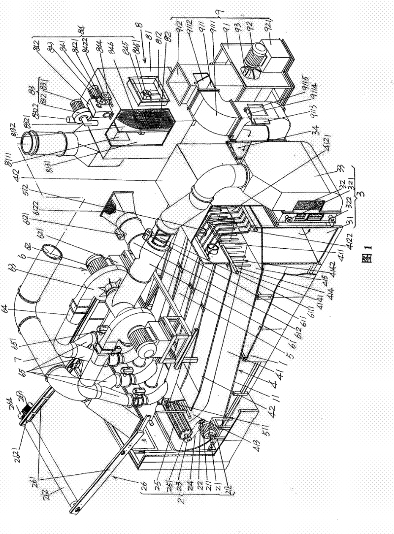
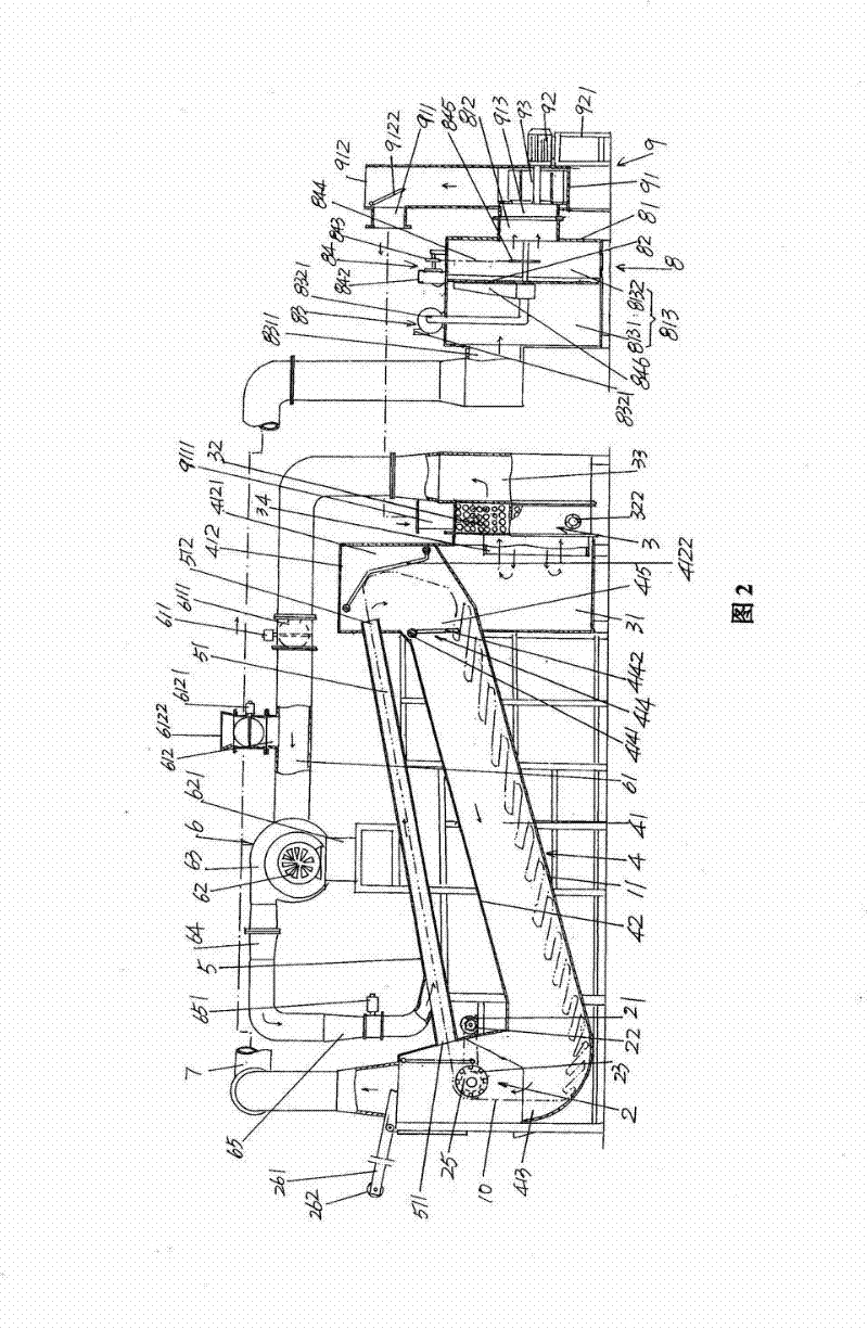
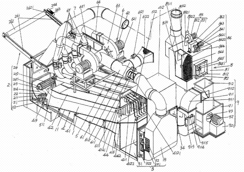
[0022] please see figure 1 with figure 2 , a chassis 1 is given, and the chassis 1 can also be called a rack (the same below). A cloth guide mechanism 2 preferably but not absolutely limited to the structure shown in the figure is arranged on the left end of the cabinet 1 (the following concepts involving left and right are all based on the position state shown in the current illustration) and an air ...


PUM


Abstract

The invention discloses an airflow fabric finishing machine belonging to the technical field of fabric finishing machines, and comprising a chassis, a fabric guiding mechanism, an air heating mechanism, a fabric guiding box, one set of Venturi pipes, a hot air guiding mechanism and a dust removing wind pipe, wherein fabric inlets and fabric outlets of pipe cavities of the Venturi pipes are connected with a fabric guiding channel; the airflow fabric finishing machine further comprises a dust removing mechanism and a returned hot air guiding mechanism composed of a wind guiding box, a wind guiding motor and a wind guiding fan; the dust removing wind pipe is connected with the dust removing mechanism; the wind guiding box is disposed on a part corresponding to the air heating mechanism and is provided with a lateral wind outlet, a discharging port and a hot air returned guiding port; the lateral wind outlet is connected with an external air wind inlet of the air heating mechanism; the discharging port is connected with the external; the hot air returned guiding port is matched with the dust removing mechanism; the wind guiding motor is fixed on the outer wall of the wind guiding box; the wind guiding fan is located in the wind guiding box and corresponds to the hot air returned guiding port. The invention has the advantages of environment friendliness, energy conservation and prevention of influence on fabrics.

Description

technical field [0001] The invention belongs to the technical field of fabric finishing machinery, and in particular relates to an airflow type fabric finishing machine. Background technique [0002] The air-flow fabric finishing machine can also be called the air-flow fabric shaker or the air-flow shaker for short. As is known in the knitting and textile industry, after the fabric is brushed, combed and sheared, it is then subjected to the shaker energy. After the surface of the fabric is piled up, the disorderly arranged fluff is curled into a granular shape, and the fluff is arranged in an orderly manner, and the wool feels plump and vertical. [0003] In the published Chinese patent literature, there is no shortage of technical information about the fabric polarizing, that is, the aforementioned fabric finishing. For example, a high-temperature and high-pressure vacuum-type shaker recommended by utility model patent authorization announcement number CN2308615Y, an impro...

Claims


Application Information

Patent Timeline
Patent Type & Authority Applications(China)
IPC IPC(8): D06C11/00
Inventor 代勇许捷恺
Owner 苏州博杰思达机械有限公司
Why Eureka
Try Eureka