
Data transmission method and equipment for carrier aggregation system

A carrier aggregation and data transmission technology, applied in the field of data transmission

Active Publication Date: 2011-11-02
DATANG MOBILE COMM EQUIP CO LTD
View PDF4 Cites 26 Cited by
  • Summary
  • Abstract
  • Description
  • Claims
  • Application Information

AI Technical Summary

Problems solved by technology

[0014] Embodiments of the present invention provide a data transmission method and device in a carrier aggregation system, which are used to solve the problem of how UE performs data transmission in subframes with uncertain uplink and downlink transmission directions

Method used


Image

  • Data transmission method and equipment for carrier aggregation system
  • Data transmission method and equipment for carrier aggregation system
  • Data transmission method and equipment for carrier aggregation system

Examples


Embodiment 1

[0094] Corresponds to method one above. Such as Image 6 As shown, the UL grant corresponding to subframe 8 is transmitted in subframe 1, and the UL grant corresponding to subframe 9 is transmitted on subframe 5.

[0095] If the UE receives the UL grant from the base station in subframe 1, the UL grant is used to schedule the UE to transmit PUSCH on the carrier of band1 in subframe 8, but does not receive the UL grant in subframe 5. The PUSCH is transmitted in subframe 8, and the PDCCH and / or PDSCH will be detected in subframe 9 of band2.

[0096] If the UE does not receive the UL grant from the base station in subframe 1 but receives the UL grant in subframe 5, the UE will detect PDCCH and / or receive PDSCH in subframe 8 in band2, and change the subframe in band1 PUSCH is transmitted on 9.

[0097] If the UE does not receive the UL grant from the base station in subframes 1 and 5, the UE will detect the PDCCH and / or receive the PDSCH in subframes 8 and 9 on band2.

[0098] If the UE...

Embodiment 2

[0100] Corresponds to the above method two.

[0101] If the UE receives the UL grant from the base station in subframe 5, and the UL grant is used to schedule the UE to transmit PUSCH on the carrier of band1 in subframe 9, the UE regards both subframes 8 and 9 as uplink subframes. The carrier on band2 detects PDCCH and / or receives PDSCH.

[0102] If the UE does not receive the UL grant from the base station in subframes 1 and 5, the UE regards subframes 8 and 9 as downlink subframes, and will detect PDCCH and / or receive PDSCH on the carrier on band2 in the above subframes .

[0103] If the UE receives the UL grant from the base station in subframe 1, the UL grant is used to schedule the UE to transmit PUSCH on the carrier of band1 in subframe 8, but does not receive the UL grant in subframe 5, then the UE treats subframe 8 as It is an uplink subframe, and subframe 9 is regarded as a downlink subframe.

[0104] See Figure 7 , An embodiment of the present invention also provides a te...


PUM


Abstract

The embodiment of the invention discloses a data transmission method and data transmission equipment for a carrier aggregation system, and relates to the technical field of wireless communication. The method and the equipment are used for solving the problem of how to transmit data in a sub-frame with an uncertain uplink / downlink transmission direction by user equipment (UE). The method comprises that: a terminal determines whether uplink scheduling signaling for the sub-frame with the uncertain uplink / downlink transmission direction is received from a base station or not; and the terminal transmits uplink data or receives downlink data by using the sub-frame with the uncertain uplink / downlink transmission direction according to a determination result. The terminal in the scheme can determine how to transmit the data in the sub-frame with the uncertain uplink / downlink transmission direction according to whether the uplink scheduling signaling is received or not, thereby solving the problem of how to transmit the data in the sub-frame with the uncertain uplink / downlink transmission direction by the UE not supporting synchronous uplink and downlink transmission.

Description

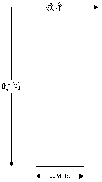
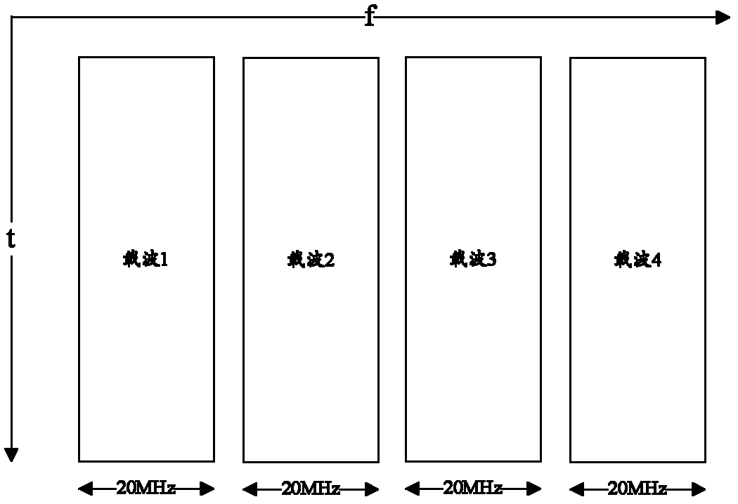
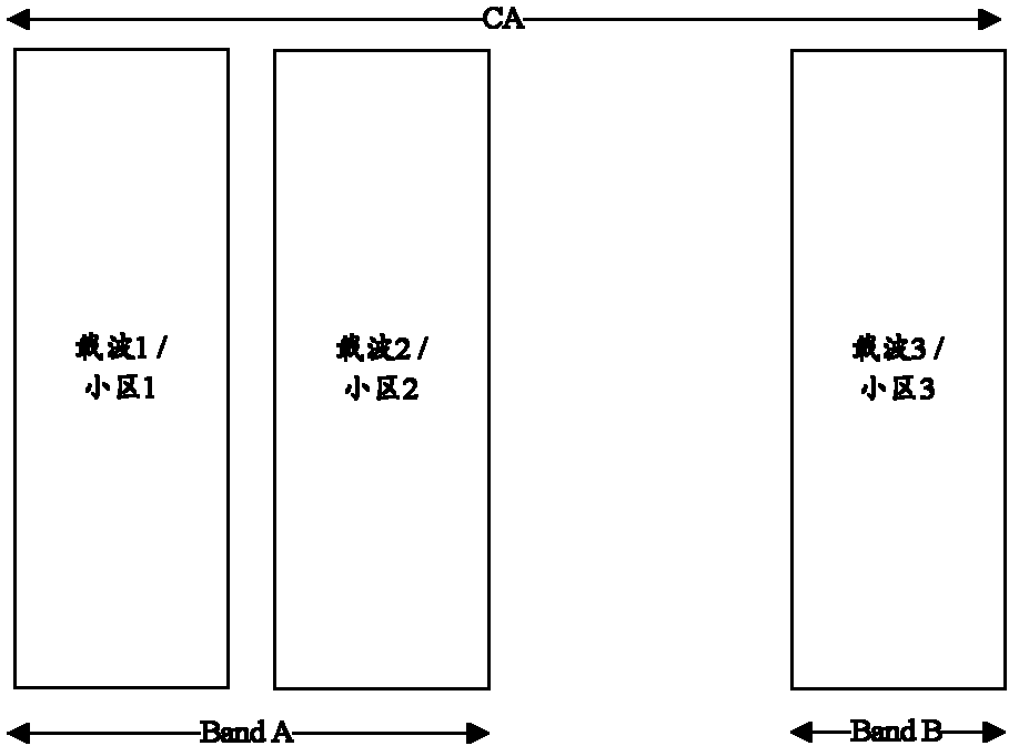
Technical field [0001] The present invention relates to the field of wireless communication, and in particular to a data transmission method and equipment in a carrier aggregation system. Background technique [0002] In the Long Term Evolution (LTE) system and previous wireless communication systems, there is only one carrier in a cell, and the maximum bandwidth in the LTE system is 20 MHz, such as figure 1 Shown. [0003] In the long-term evolution upgrade (LTE-A, LTE Advanced) system, the peak rate of the system is greatly improved compared with the LTE system, and it is required to reach 1Gbps in the downlink and 500Mbps in the uplink. If only a carrier with a maximum bandwidth of 20MHz is used, the peak rate requirement cannot be achieved. Therefore, the LTE-A system needs to expand the bandwidth that can be used by the terminal, and thus introduces Carrier Aggregation (CA) technology, that is, multiple continuous or discontinuous carriers under the same base station (eNB) ar...

Claims


Application Information

Patent Timeline
IPC IPC(8): H04B7/26H04W72/12
CPCH04W72/0446H04W72/1205H04L5/001H04L5/0044H04L5/0091H04W72/12
Inventor 林亚男潘学明沈祖康丁昱
Owner DATANG MOBILE COMM EQUIP CO LTD
Learn More