Thread guiding device for a thread changing device

A thread adjusting device and yarn guide technology are used in textile and papermaking, weft knitting, knitting and other directions, which can solve the problems of reducing the knitting system and the inability to use the knitting time economically, and achieve the goal of increasing the number and the width of the small structure. Effect

Active Publication Date: 2015-01-21
SIPRA PATENTENTWICKLUNGS & BET GMBH
View PDF10 Cites 0 Cited by
  • Summary
  • Abstract
  • Description
  • Claims
  • Application Information

AI Technical Summary

Problems solved by technology

The resulting widening of the thread adjustment device would result in a reduction of the knitting system that can be used on the machine, which cannot be used economically due to the associated increase in knitting time

Method used


Image

  • Thread guiding device for a thread changing device
  • Thread guiding device for a thread changing device
  • Thread guiding device for a thread changing device

Examples


Embodiment Construction

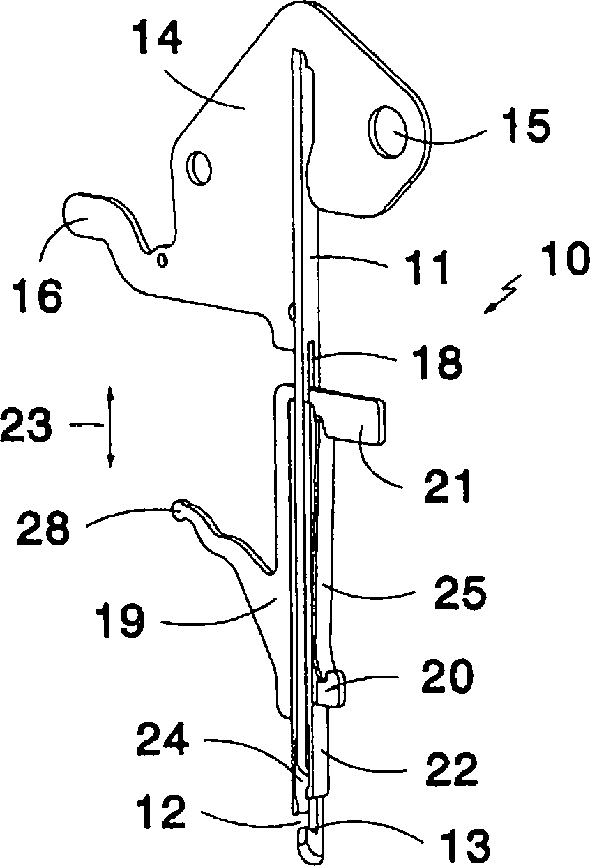
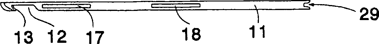
[0025] figure 1 The shown thread guide 10 has a finger 11 which has a thread receiving area 12 on its front end in the form of a substantially U-shaped recess, which is in particular composed of Figure 2b visible. The front boundary of the cutout 12 is formed as a cutting edge 13 . The rear end of the finger 11 is fastened to a pivot lever 14 which has a hole 15 for receiving a pivot axis of the thread adjustment device which is not described in detail here. Furthermore, it is provided with an actuating foot 16 for triggering the pivoting movement. In the finger body 11, two Figure 2b Visible longitudinal slits 17, 18, of which the longitudinal slit 18 is also figure 1 visible in . A guide element 19 is inserted in the longitudinal slot 17 , 18 and passes through the longitudinal slot 17 , 18 with two projections 20 , 21 . A clamping element 24 is arranged between the guide element 19 and the finger 11 . On the other side of the finger 11 opposite the clamping element...


PUM


Abstract

#CMT# # / CMT# The thread finger (10) has an elongated finger body (11) with an end fastened at a pivotal lever (14), where other end of the finger body includes a thread receiving area (12) for a knitting thread. A guide element (19) is movable along the finger body. A cutting knife (22) and a clamping element (24) are movable together with the guide element, where the clamping element is prestressed by spring force. The finger body is formed with a longitudinal slot (18). The guide element is displaceably supported in the longitudinal slot, where the finger body is formed as a metallic sheet punched part. #CMT#USE : # / CMT# Thread finger for use in a thread changing device of a knitting machine (all claimed). #CMT#ADVANTAGE : # / CMT# The guide element is displaceably supported in the longitudinal slot of the finger body, thus reducing installation space of the thread finger, and hence increasing the number of thread fingers provided in the thread changing device of the knitting machine. The thread finger ensures that increase of the number of thread fingers increases the processable knitting threads without reducing power of the knitting machine, thus reducing knitting cost and time of the knitting threads. #CMT#DESCRIPTION OF DRAWINGS : # / CMT# The drawing shows a side perspective view of a thread finger. 10 : Thread finger 11 : Elongated finger body 12 : Thread receiving area 14 : Pivotal lever 18 : Longitudinal slot 19 : Guide element 22 : Cutting knife 24 : Clamping element.

Description

technical field [0001] The invention relates to a yarn guide (Fadenfinger) of a thread adjusting device of a knitting machine, comprising an elongated finger, one end of which is fixed on a pivot rod, and the other end of which has a yarn of the knitting yarn The thread receiving area, and the yarn guide includes a guide element movably supported along the finger body, and the blade and the elastically prestressed clamping element can move along the finger body through the guide element. Background technique [0002] Such a yarn guide is known from the thread changing device of DE 195 11 949 B4. In order to push the blade and the clamping element towards the knitting yarn passing through the yarn receiving area, hollow box-shaped guides are provided around the fingers of the known thread guide, which receive the fingers in a sliding fit and In addition, the blade and the spring-loaded clamping element are arranged in the guide body so that they can be moved along the finger...

Claims


Application Information

Patent Timeline
Patent Type & Authority Patents(China)
IPC IPC(8): D04B15/60
CPCD04B15/60
Inventor H·柯尼希B·博斯
Owner SIPRA PATENTENTWICKLUNGS & BET GMBH
Why Eureka
Try Eureka