

Brake positioning control method and positioning mechanism for engine
A positioning mechanism and brake technology, which is applied in the direction of engine control, engine components, machine/engine, etc., can solve the problems of unbalanced switching between the two states of the engine, large space, etc., and achieve the effect of small space occupation and convenient installation and portability
- Summary
- Abstract
- Description
- Claims
- Application Information
AI Technical Summary
Problems solved by technology
Method used
Image

Examples
Embodiment 1
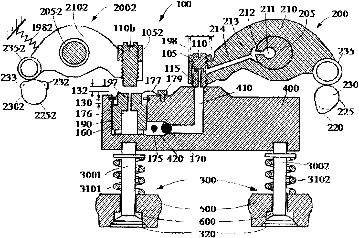
[0030] like figure 2 Shown: the engine brake positioning control method of the present invention includes a process of changing the position of the brake rocker arm in the engine brake, the engine includes an exhaust valve actuator and an exhaust valve system, and the engine brake It also includes the driving mechanism of brake cam, cam follower, rocker shaft and engine brake, wherein, in the process of changing the position of the brake rocker arm in the engine brake, when the engine is required to work normally, the One end of the brake rocker arm is separated from the brake cam, so that the other end of the brake rocker arm is separated from a brake pad. When engine braking is required, the gap between the brake rocker arm and the brake cam is eliminated, and the brake rocker The gap between the arm and the brake pad.
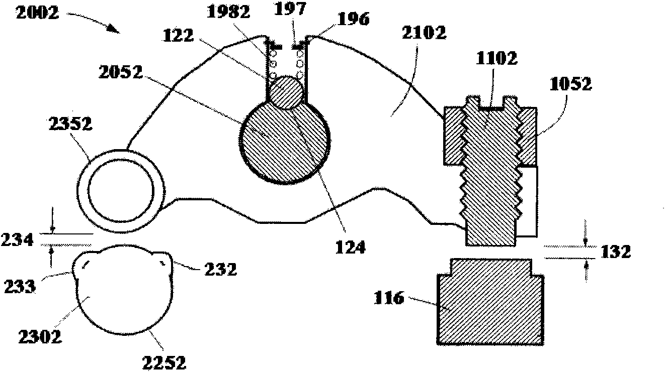
[0031] Further, a torque is set on the brake rocker arm, and the torque causes one end of the brake rocker arm to separate from the brake cam, and the oth...
Embodiment 2
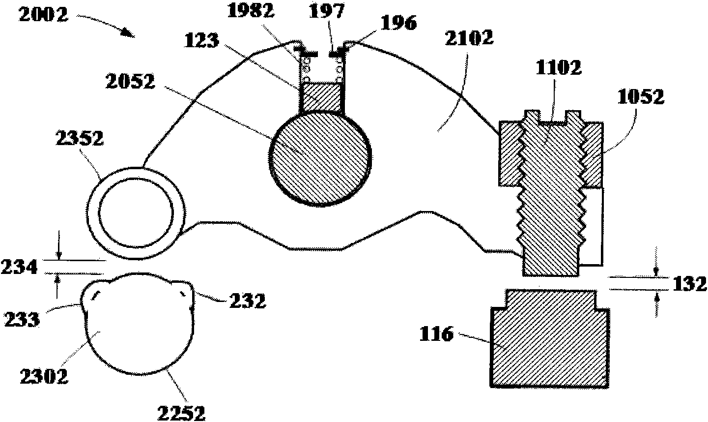
[0037] like image 3 As shown, the difference between this embodiment and the first embodiment is that the pressure ball 122 is replaced by a pressure block 123, and a hole is opened in the middle of the brake rocker arm 2052 along its radial direction, and the inner end of the hole reaches the rocker shaft, and the pressure The block 123 is set in the hole and is in contact with the rocker shaft 2052, the spring 1982 is set in the hole, the outer end 1982 of the spring is fixedly connected with the brake rocker arm 2052, the inner end 1982 of the spring is in contact with the pressing block 123, and the pressing block 123 directly Acts on the cylindrical surface of the rocker shaft 2052. In this embodiment, the principle of brake positioning is to rely on the frictional damping between the positioning pressure block 123 and the rocker shaft 2052 for automatic positioning. When the engine is turned from the braking state to the non-braking state, the rocker arm 2102 will find...
Embodiment 3
[0039] like Figure 4 As shown, the present embodiment also adopts the automatic positioning of friction damping. The positioning pressure block 126 is in contact with the side surface 125 of the brake rocker arm 2102, and the brake spring 1982 is installed on the rocker arm shaft 1052, between the brake rocker arm 2102 and the intake rocker arm 2103, and the spring is in a compressed state.
PUM
 Abstract
Description
Claims
Application Information