
Apparatus for capturing and harnessing the energy from environmental wind

a technology of environmental wind and equipment, applied in the direction of wind energy generation, mechanical equipment, machines/engines, etc., can solve the problems of difficult to generate significant wind energy, need to be located away from populous areas, and high cost of equipmen

Inactive Publication Date: 2003-08-21
VERINI NICHOLAS A
View PDF4 Cites 44 Cited by
  • Summary
  • Abstract
  • Description
  • Claims
  • Application Information

AI Technical Summary

Benefits of technology

[0013] In one modification of the invention, the apparatus further includes an airflow velocity-sensing element disposed in the conduit for measuring the airflow speed therein. Moreover, an airflow speed control member is also disposed therein proximate the conduit first end portion to selectively restrict and dampen the speed of the airflow received by the turbine device from the conduit in response to variable speed changes in and gusts of environmental wind impacting the collector air inlet conduit. In one variation of this, the airflow speed control member may be in the form of a dampening device disposed in the conduit to prevent sudden impact of airflow onto the wind turbine device resulting from substantial gusts of environmental wind entering the wind collector, the dampening device being selectively movable between a full open position unaffecting conduit airflow speed to a full closed position blocking conduit airflow entirely.
[0019] In a further modification of the invention, the device further includes an airflow velocity sensing element disposed in the conduit for measuring the airflow speed therein, and an airflow speed control member disposed proximate the conduit first end portion to regulate the speed of the airflow in the conduit in response to variable speed changes in and gusts of environmental wind impacting the collector air inlet to prevent sudden speed changes in the airflow impacting the turbine device. In one form, the airflow speed control member may comprise a dampening device disposed in the conduit to prevent sudden impact of airflow onto said wind turbine device resulting from substantial gusts of environmental wind entering the wind collector, the dampening device being selectively movable between a full open position unaffecting conduit airflow speed to a full closed position blocking conduit airflow entirely. In addition, the device of the invention may be adapted for association with a residential housing unit with the tower member being in the form of a substantially vertical tube. Moreover, the tower member may be directly incorporated as an integral component of the residential housing unit with the conduit second end portion and wind turbine device being disposed at ground level. Finally, the wind collector air inlet may include a mechanism for preventing the entry of living creatures therein.

Problems solved by technology

However, to date it has been very difficult to generate significant energy from wind sources due to inefficiencies of wind turbine devices as well as the lack of prevalent winds on a consistent basis in many geographical locations.
One problem with the present standard wind turbine is that it needs to be located away from populous areas.
Such devices are expensive, large, loud, kill birds and somehow seem dangerous.
Again, a common problem with such systems is the lack of consistent prevalent winds to power the windmill blades.
Moreover, significant noise problems were created by such windmill towers in residential neighborhoods, not to mention the unsightly nature of such devices.

Method used


Image

  • Apparatus for capturing and harnessing the energy from environmental wind
  • Apparatus for capturing and harnessing the energy from environmental wind
  • Apparatus for capturing and harnessing the energy from environmental wind

Examples


Embodiment Construction

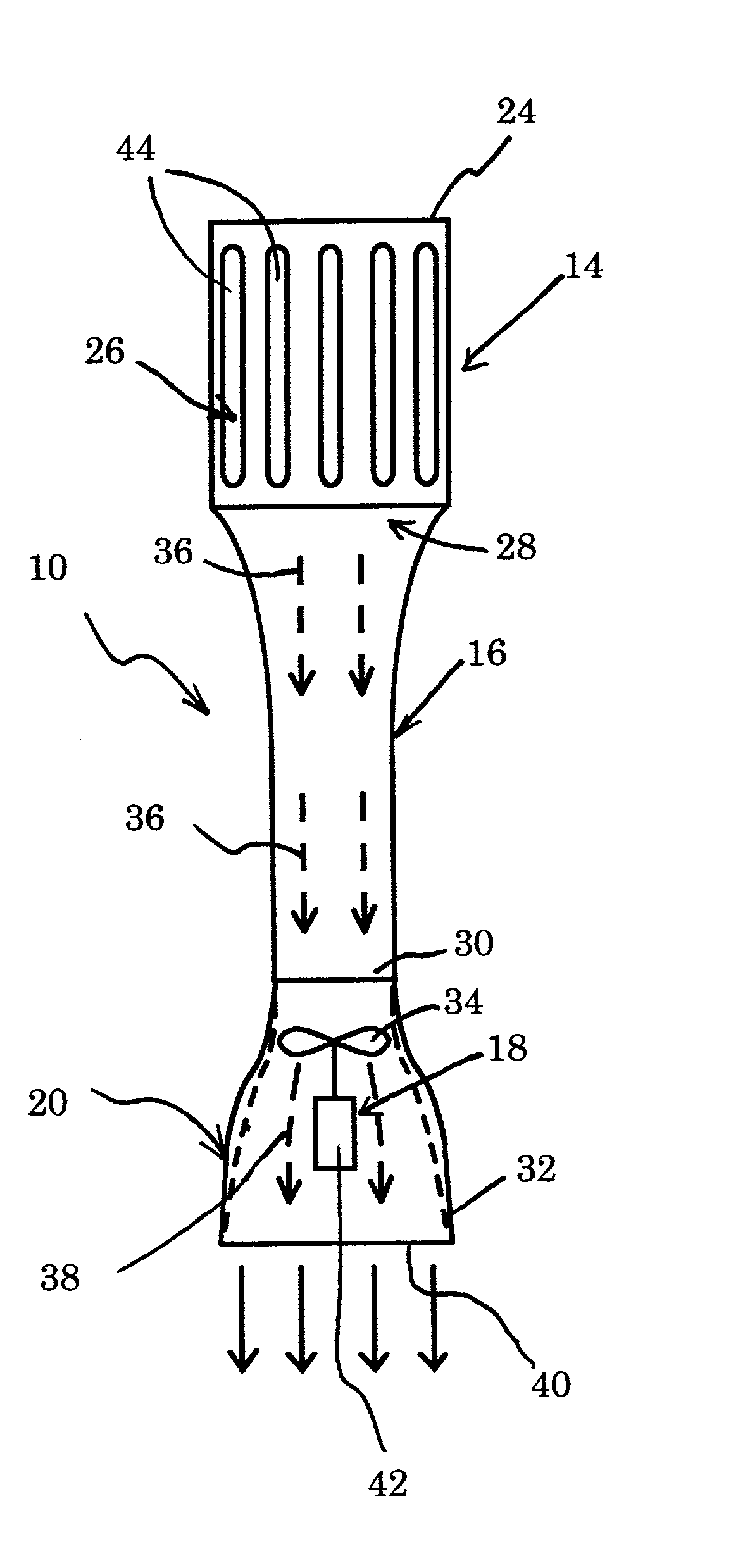
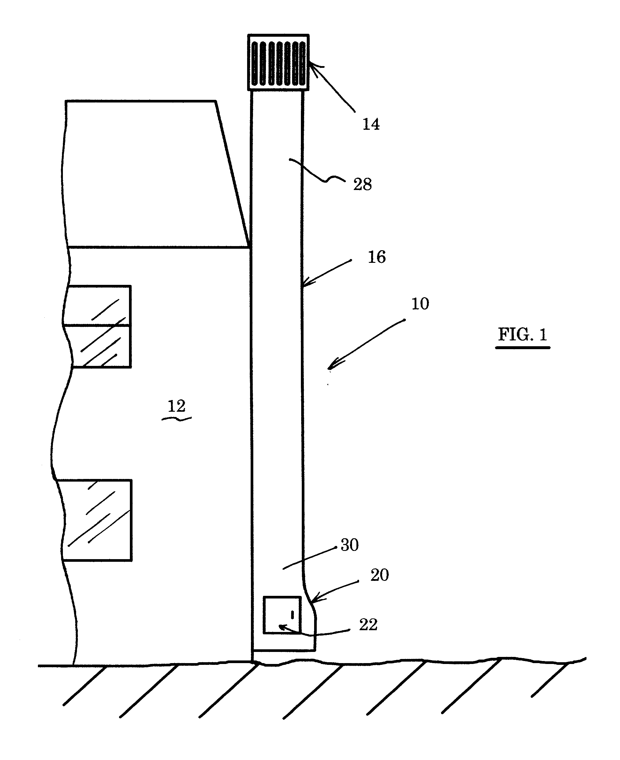
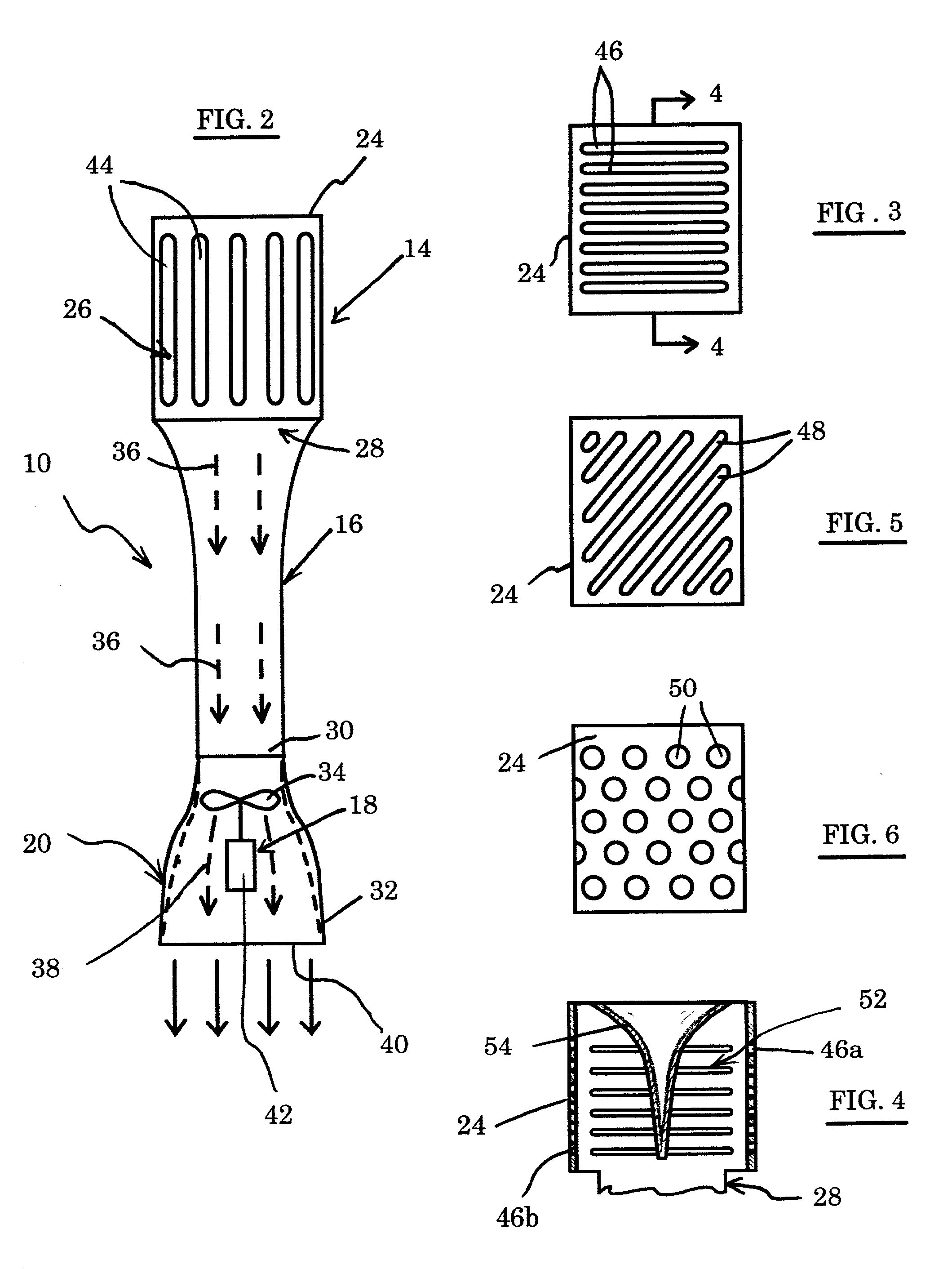
[0035] Referring first to FIGS. 1 and 2, a device 10 is illustrated for capturing and converting wind energy to electrical energy. In one preferred embodiment, the device 10 is attached to or made an integral part of a residential structure 12. It should be understood, however, that the device 10 may be associated with the residential structure 12 in any manner desired. Moreover, it may also be formed as a freestanding member apart from any particular specific structure.

[0036] In one preferred form, the device 10 includes a wind collector 14 mounted to the uppermost end of a tower 16. A wind turbine 18 is preferably mounted in the lowermost portion 20 of the tower 16. In the embodiment illustrated in FIG. 1, an access door 22 is disposed in the lowermost portion 20 to provide ready access to the turbine 18. While the tower 16 is illustrated in a preferred form wherein it is an upright, vertical member, it should be understood that the tower 16 may be oriented at any desired angle, i...


PUM


Abstract

An apparatus is disclosed for capturing and converting wind energy to electrical energy. The apparatus includes a tower member arranged in the form of an elongated conduit having first and second end portions. A wind collector is provided and is associated with the conduit first end portion. The wind collector has an air inlet to capture environmental wind originating from one or more directions and then deflect the captured wind into the conduit to create an axial airflow therein. Finally, a wind turbine device is disposed at the conduit second end portion for receiving the airflow from the conduit in order to generate electricity therefrom.

Description

[0001] 1. Field of the Invention[0002] The present invention relates generally to devices for converting wind energy to electrical energy and, more particularly, to systems utilizing wind driven turbine generators. Specifically, the present invention relates to devices adapted to capture environmental wind and harness its energy for residential use.[0003] 2. Description of the Prior Art[0004] In the last several decades, considerable attention has been given to non-petroleum forms of energy generation and in particular to renewable forms of energy. Such renewable energy sources include biomass conversion systems, passive and active solar energy devices, and wind energy driven systems. Wind driven turbines and windmills have been used for centuries to capture energy and generate power. There have been constant efforts to increase the efficiency of and hence the energy production from wind turbines. However, to date it has been very difficult to generate significant energy from wind s...

Claims


Application Information

Patent Timeline
Patent Type & Authority Applications(United States)
IPC IPC(8): F03D1/04
CPCF03D1/04Y02E10/72F05B2240/133F05B2240/131Y02E10/728F03D9/35F03D17/00
Inventor VERINI, NICHOLAS A.
Owner VERINI NICHOLAS A
Learn More