
Internal combustion engine with liquid cooling

An internal combustion engine, liquid cooling technology, used in liquid cooling, engine components, machines/engines, etc., can solve problems such as unused, dissipation, etc., to achieve the effect of improving operation

Active Publication Date: 2011-11-09
FORD GLOBAL TECH LLC
View PDF5 Cites 12 Cited by
  • Summary
  • Abstract
  • Description
  • Claims
  • Application Information

AI Technical Summary

Problems solved by technology

In the prior art, more than a quarter of the energy used is dissipated in the coolant of the liquid cooling structure, that is, usually to the cooling water, and is dissipated to the environment, unused

Method used


Image

  • Internal combustion engine with liquid cooling
  • Internal combustion engine with liquid cooling
  • Internal combustion engine with liquid cooling

Examples


Embodiment Construction

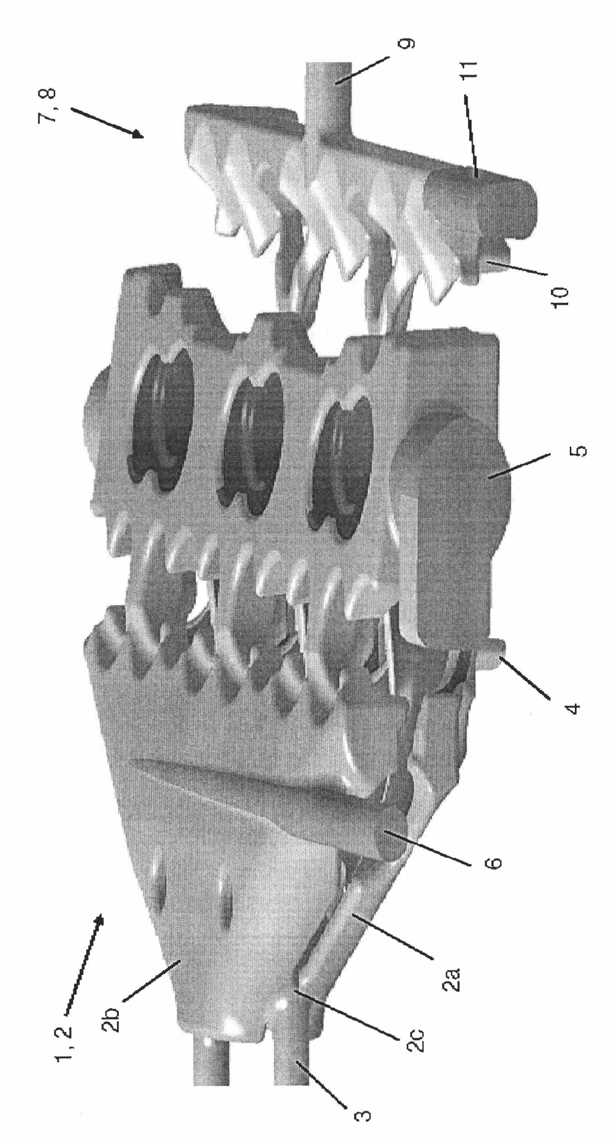
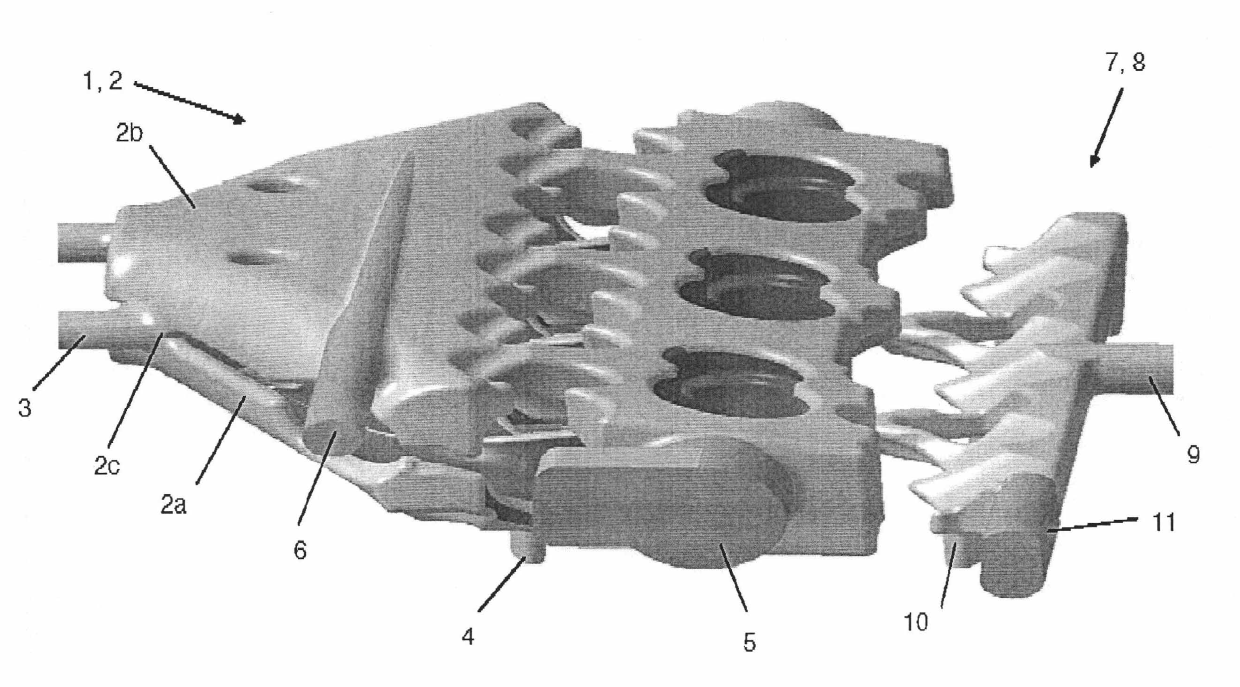
[0123] figure 1 A slightly inclined plan view showing the sand cores 1 , 7 of the cooling jackets 2 , 8 of the two coolant circuits separated from one another according to the first embodiment, which are integrated in the cylinder head of the internal combustion engine.

[0124] With the aid of sand cores 1, 7, figure 1 The components of the two cooling circuits, which are integrated in the finished cylinder head and in particular in the respective cooling jacket 2 , 8 , are also schematically shown. For this purpose, the sand cores 1 , 7 are also provided with identification numbers associated with the cooling jackets 2 , 8 .

[0125] In order to form a liquid cooling structure, two cooling jackets 2a, 2b are arranged on the outlet side of the cylinder head, and one cooling jacket 8 is arranged on the inlet side of the cylinder head, the two outlet side cooling jackets 2a, 2b belong to the cooling water circuit, On the other hand, the cooling jacket 8 on the inlet side is p...


PUM


Abstract

The invention relates to an internal combustion engine with at least a cylinder, the engine comprises: at least one cylinder cover, and a liquid cooling structure, the liquid cooling structure is provided with at least two coolant jackets (2, 8) integrated in the cylinder cover, wherein each cylinder is provided with at least one air outlet used for discharging exhaust at an outlet side, and at least an air inlet used for supplying fresh air at the inlet side. The invention aims at providing the internal combustion engine in the above type, and optimization is obtained in two aspects of cooling and wearing. In order to realize the purpose, the internal combustion engine is characterized in that, in the cylinder cover, at least a coolant jacket (2) is disposed at the outlet side and at least a coolant jacket (8) is disposed at the inlet side, wherein at least two coolant jackets (2, 8) are spaced part and belong to different independent coolant circuits.

Description

technical field [0001] The invention relates to an internal combustion engine with at least one cylinder, comprising: at least one cylinder head, and a liquid cooling structure with at least two cooling jackets integrated in the cylinder head, each cylinder having at least one gas outlet on the outlet side for It is used for discharging exhaust gas and has an air inlet on the inlet side for supplying fresh air. Background technique [0002] An internal combustion engine of the above-mentioned type is used as drive for a motor vehicle. In the context of the present invention, the term "internal combustion engine" includes diesel engines and spark ignition engines, as well as mixed fuel internal combustion engines, ie internal combustion engines which operate with a mixed combustion process. [0003] The internal combustion engine has a cylinder head and a cylinder block, which are connected to one another at the assembly end side to form a single cylinder. [0004] Cylinder...

Claims


Application Information

Patent Timeline
Patent Type & Authority Applications(China)
IPC IPC(8): F01P3/02
CPCF01P7/165F01P3/02F01P2003/024F01P2003/008
Inventor B·施泰纳K·库荷尔巴茨J·梅林
Owner FORD GLOBAL TECH LLC
Learn More