
winding device

A winding and winding end technology, applied in the direction of shape/style/structure of electromechanical devices, electric components, winding conductors, etc., can solve unsatisfactory problems, increase the total cost of stator winding configuration, etc., and achieve total weight reduction and total loss The effect of reducing and increasing the overall performance

Active Publication Date: 2015-09-23
SIEMENS GAMESA RENEWABLE ENERGY AS
View PDF4 Cites 0 Cited by
  • Summary
  • Abstract
  • Description
  • Claims
  • Application Information

AI Technical Summary

Problems solved by technology

Obviously this increases the overall cost of the stator winding arrangement and is therefore not satisfactory

Method used


Image

  • winding device
  • winding device
  • winding device

Examples


Embodiment Construction

[0027] figure 1A very simple diagram of a generator 4 in a wind turbine 5 is shown. For simplicity, only relevant components are represented, other components such as gearbox, controller etc. are not shown. Pressure applied to the blades 50 of the wind turbine 5 turns the hub 51 or mandrel and thus the rotor 3 . The rotor 3 is surrounded by the stator 2 around which a plurality of coils (not shown) are wound. The generator 4 acts as an induction motor, in which a current is induced in the coils. The principle of operation of such a generator will be clear to a person skilled in the art and thus need not be described in detail here.

[0028] Due to the large currents (eg around 200-500 Amps for a 2-10 MW wind turbine), the windings have to be dimensioned accordingly. For wind turbine stators, the windings are usually made of stacked metal bars or strips with a cross-section of approximately 20 mm × 100 mm. These strips are held in stator slots arranged around the outside o...


PUM


Abstract

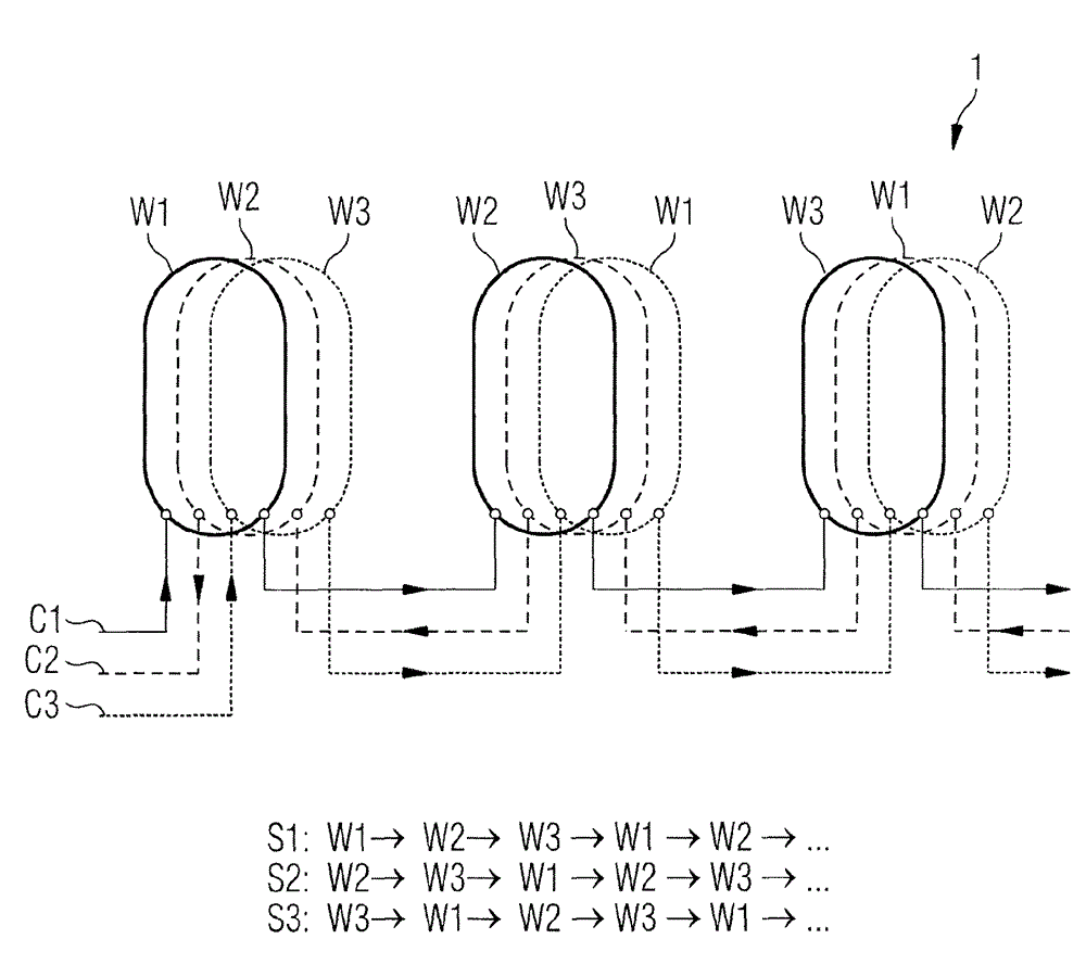
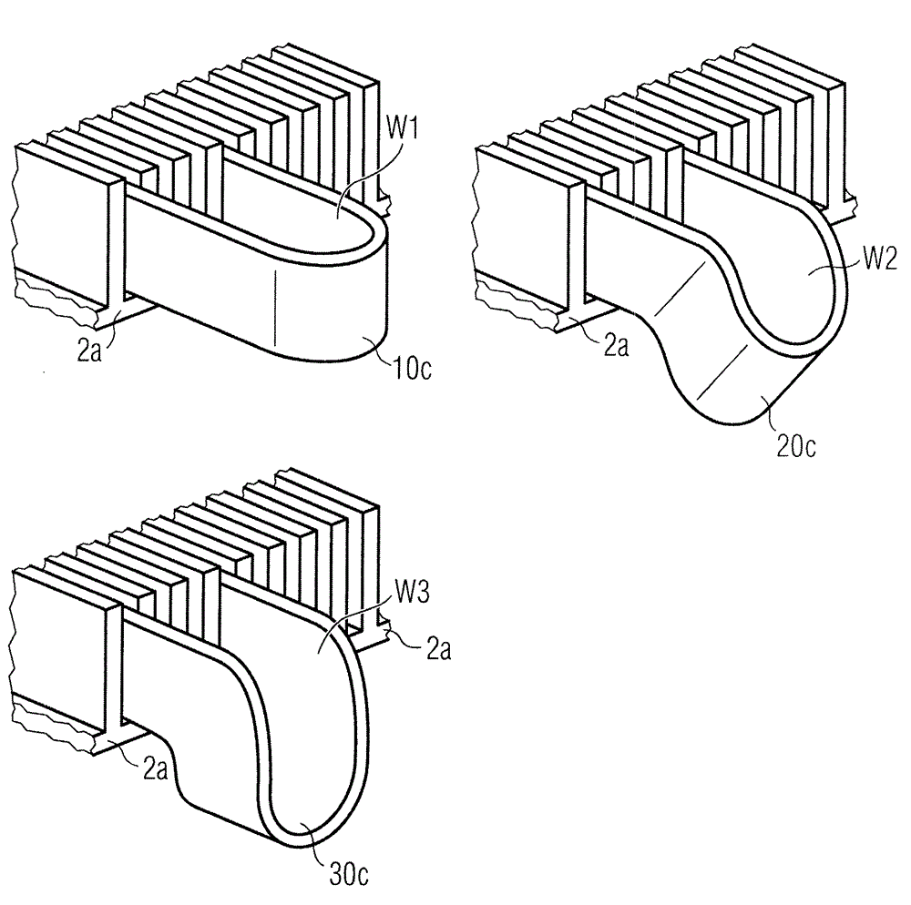
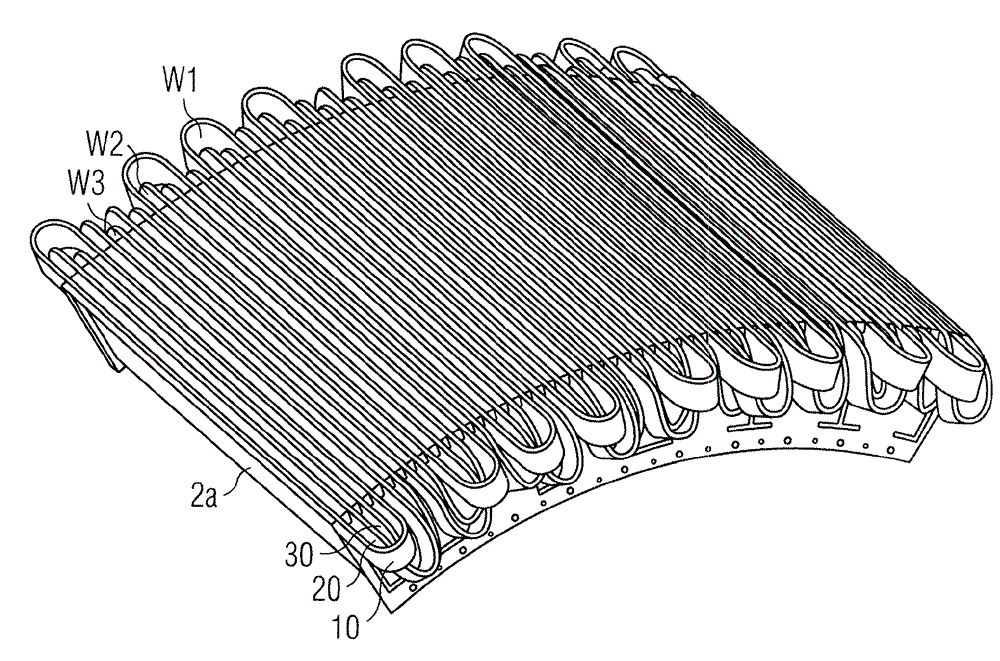
The invention describes a winding arrangement (1) for an armature (2) of an electric machine (4), which winding arrangement (1) comprises a plurality of coils (C1, C2, C3) and a plurality of distinct winding types (W1, W2, W3), wherein the coils (C1, C2, C3) are arranged on the armature (2) such that each coil (10, 20, 30) comprises the same number of windings (10, 20, 30) and the same number of each of the distinct winding types (W1, W2, W3). The invention further describes an armature (2) for a generator (4), comprising a plurality of coils (C1, C2, C3), wherein the coils (C1, C2, C3) are arranged on the armature (2) according to such a winding arrangement. The invention also describes a wind turbine (5) with a generator (4) comprising a rotor (3) and a stator (2), and wherein a plurality of coils (C1, C2, C3) is arranged on the stator (2) according to such a winding arrangement.

Description

technical field [0001] The invention describes a winding arrangement for an armature of an electric motor. The invention further describes an armature for a generator and a wind turbine with a generator. Background technique [0002] For large armatures such as the rotor or stator of a wind turbine, the coil windings are usually very thick and heavy due to the physical size of the generator and the large currents induced. The windings may be made of thick wire, such as stranded wire, which is then wound onto the armature, usually onto the stator. To this end, the armature is usually made of a number of parallel slots arranged axially along the outside to accommodate the windings. Instead of winding wire onto the armature, preformed windings can be formed and inserted or "dropped" into slots in the armature. Such preformed windings generally comprise a closed loop comprising a "forward" portion and a "return" portion held in the two armature slots. The coil comprises a pl...

Claims


Application Information

Patent Timeline
Patent Type & Authority Patents(China)
IPC IPC(8): H02K3/12
CPCH02K2213/12Y02E10/725H02K3/12H02K7/1838Y02E10/72
Inventor J·K·布思
Owner SIEMENS GAMESA RENEWABLE ENERGY AS
Learn More