Supercharge Your Innovation With Domain-Expert AI Agents!

Radiating device

A heat dissipation device and heat conduction plate technology, which is applied to indirect heat exchangers, lighting and heating equipment, cooling/ventilation/heating transformation, etc., can solve the problems of cumbersome manufacturing process of heat dissipation devices, unfavorable rapid mass production, etc., and achieve saving in manufacturing processes , Reduce the effect of the manufacturing process

Inactive Publication Date: 2011-11-09
FU ZHUN PRECISION IND SHENZHEN +1
View PDF6 Cites 1 Cited by
  • Summary
  • Abstract
  • Description
  • Claims
  • Application Information

AI Technical Summary

Problems solved by technology

Since there is no connection between the bottom plate and the base that can be positioned with each other, jigs must be used to pre-fix the bottom plate on the base before welding, resulting in a cumbersome manufacturing process for the heat sink, which is not conducive to rapid mass production

Method used


Image

  • Radiating device
  • Radiating device
  • Radiating device

Examples


Embodiment Construction

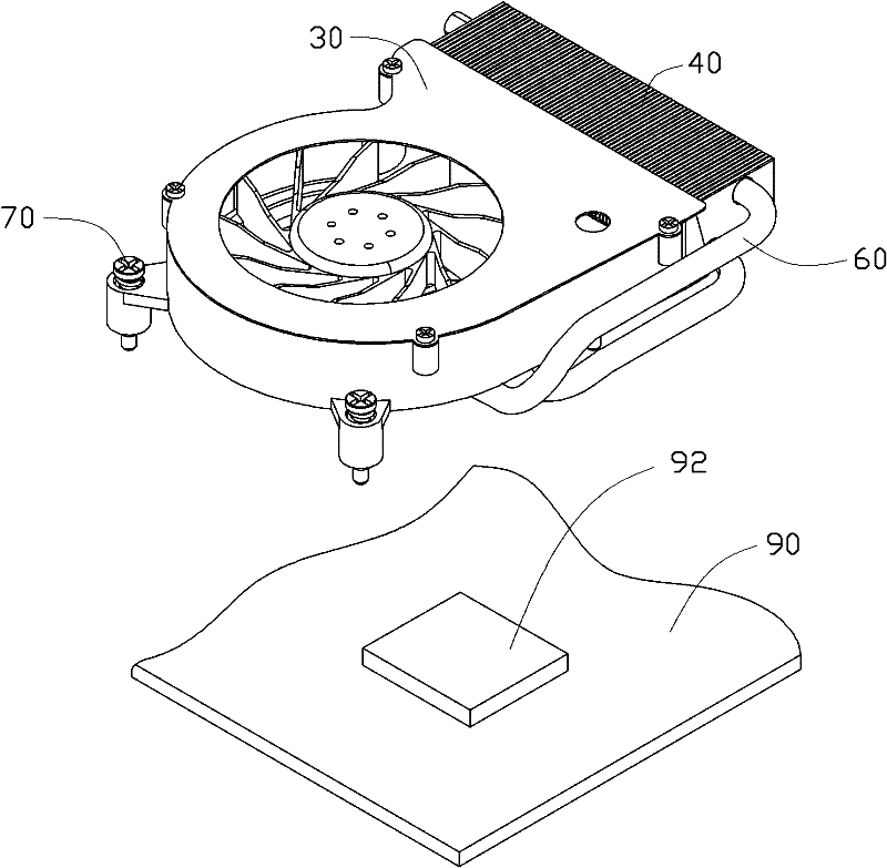
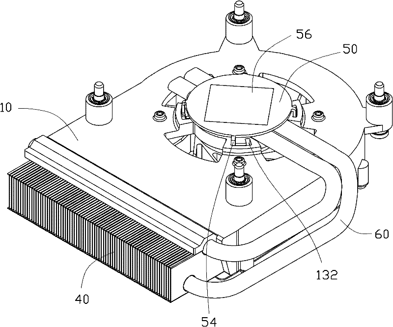
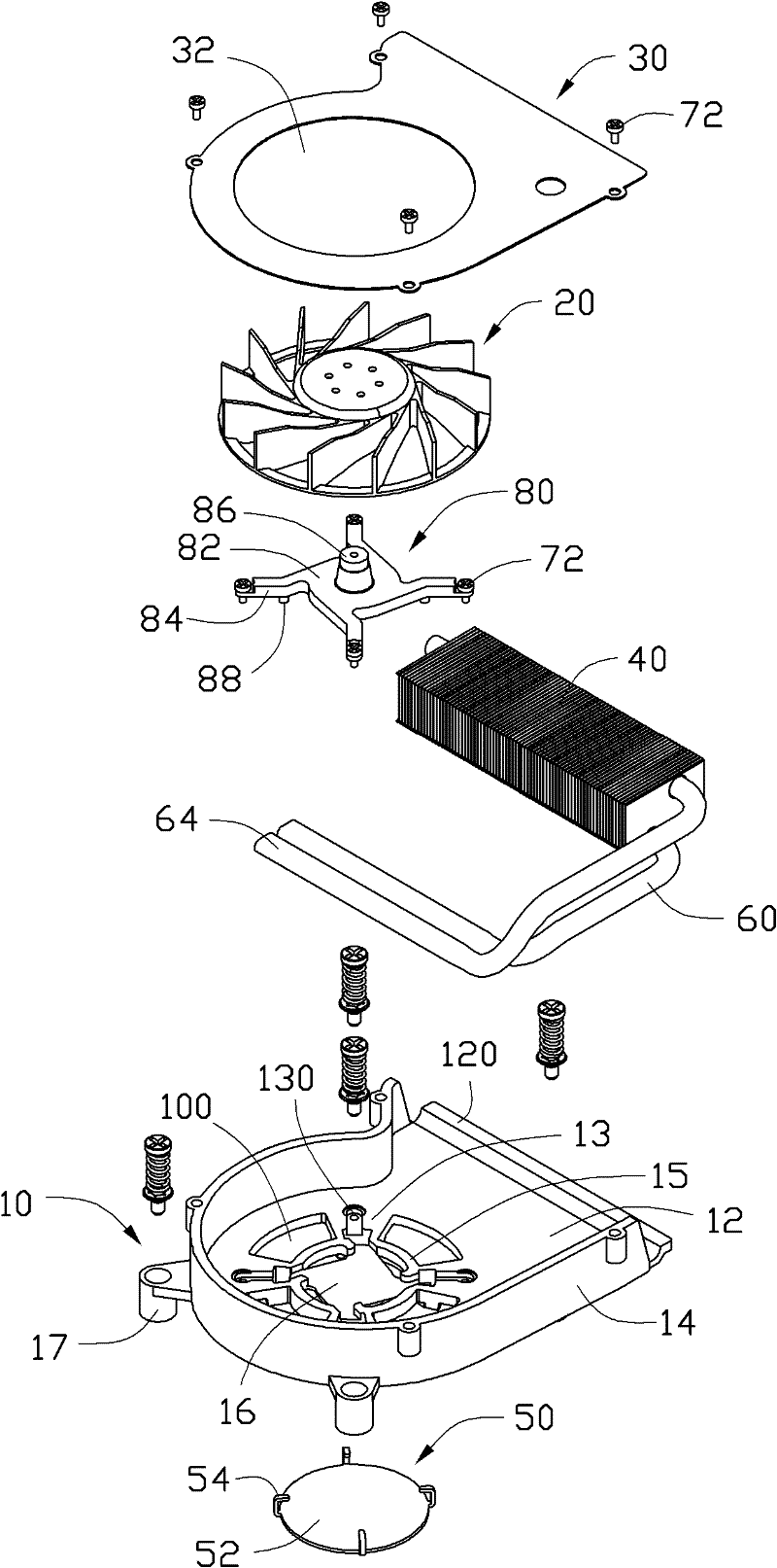
[0016] see Figure 1-3 , which shows the heat dissipation device of the present invention. The heat dissipation device includes a base 10, a fan 20 accommodated in the base 10, a cover plate 30 covering the base 10, a fin set 40 fixed on the base 10, a fin set 40 fixed on the base 10 The base plate 50 at the bottom and two heat pipes 60 connecting the fin set 40 and the base plate 50 .

[0017] Please also refer to Figure 4 , the base 10 includes a base 12 and a sidewall 14 vertically extending upward from the periphery of the base 12 . The base 12 is formed by connecting a circular part and a rectangular part. The base 12 defines a circular opening 100 in the middle area of ​​the circular portion, and a rectangular plate 16 concave relative to the base 12 is provided in the middle of the opening 100 . A ring wall 18 is formed around the plate body 16 , the plate body 16 is connected to the inner side of the ring wall 18 through its four corners, and the outer side of the...


PUM


Abstract

A radiating device is used for radiating an electronic element and comprises a base, and a bottom plate for contacting the electronic element, wherein the bottom plate comprises a heat-conducting plate and a plurality of buckling pins extending from the heat-conducting plate; and the plurality of buckling pins are inserted into the base and are used for buckling the bottom plate onto the base. The radiating device provided by the invention can save the manufacturing process and is favorable for quick batch production.

Description

technical field [0001] The invention relates to a heat dissipation device, in particular to a heat dissipation device for electronic components. Background technique [0002] As the heat generated by the current electronic components is increasing, if it cannot be effectively dissipated, it will easily lead to overheating of the electronic components, resulting in unstable work or even burning out. Therefore, heat sinks are usually installed on electronic components to dissipate heat. [0003] A conventional heat dissipation device generally includes a base and a plurality of heat dissipation fins formed on the base. In addition, in order to allow the base to conduct heat more fully, a bottom plate with an area equivalent to the electronic components is usually installed under the base. By contacting the bottom plate with the electronic components, the heat of the electronic components can be conducted to the base more evenly, and then dissipated through the fins. [0004...

Claims


Application Information

Patent Timeline
Patent Type & Authority Applications(China)
IPC IPC(8): H05K7/20
CPCH01L23/427H01L23/4006H01L23/467F28D15/0275F28D15/0266H01L2924/0002H01L2924/00
Inventor 杨健
Owner FU ZHUN PRECISION IND SHENZHEN
Features
  • R&D
  • Intellectual Property
  • Life Sciences
  • Materials
  • Tech Scout
  • Unparalleled Data Quality
  • Higher Quality Content
  • 60% Fewer Hallucinations
Learn More