Spiral concentrator

A technology of spiral concentrator and spiral groove, which is used in solid separation, wet separation, chemical instruments and methods, etc., can solve the problems of small processing capacity of single machine, weakened lateral circulation, and limited classification of particle size, etc., and achieves production cost. Low, long service life, strong wear resistance effect

Inactive Publication Date: 2011-11-16
广州粤有研矿物资源科技有限公司
View PDF5 Cites 7 Cited by
  • Summary
  • Abstract
  • Description
  • Claims
  • Application Information

AI Technical Summary

Problems solved by technology

The spiral concentrator with cubic parabola has a wide and gentle sorting surface, which weakens the lateral circulation. Once heavy minerals enter the outer edge, they cannot enter the inner edge under the action of lateral circulation and are lost.
The spiral concentrator with compound curve has a relatively large lateral inclination. When processing coarse and medium-grained materials, a large number of ore particles are often concentrated on the groove surface near the inner edge, and it is difficult to intercept the concentrate.
Moreover, the currently used spiral concentrator has a small stand-alone processing capacity, limited particle size selection, and short service life.

Method used


Image

  • Spiral concentrator
  • Spiral concentrator
  • Spiral concentrator

Examples


Embodiment Construction

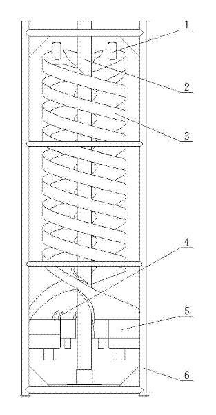
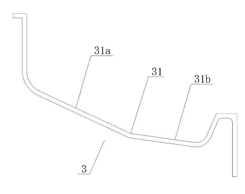
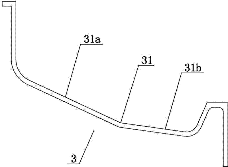
[0013] Such as Figure 1-Figure 2 As shown, the spiral concentrator of the present invention includes a frame 6, a center pipe 2 arranged on the frame 6, a spiral groove 3 fixedly connected to the center pipe 2, and a feed bucket arranged at the upper end of the spiral groove 3 1. The ore-connecting bucket 5 at the lower end, in which the center pipe 2 is located at the center of the frame 6 and its upper and lower ends are respectively connected and fixed with the upper and lower ends of the frame 6, while the spiral groove 3 adopts double ends, and the spiral groove 3. The cross section of the sorting surface 31 is composed of a straight line 31a near the outer edge and a straight line 31b near the inner edge, and the straight line 31a near the outer edge and the straight line 31b near the inner edge are respectively inclined from outside to inside. Through such arrangement, the sorting surface 31 of the spiral groove 3 is composed of two inclined planes with different later...


PUM


Abstract

The invention relates to a spiral concentrator comprising a stand, a central tube, a spiral groove, an ore feeding bucket and an ore receiving bucket, wherein the central tube is arranged on the stand; the spiral groove is fixedly connected with the central tube; the ore feeding bucket is arranged on the upper end of the spiral groove; the ore receiving bucket is arranged on the lower end of the spiral groove; the cross section of the separation surface of the spiral groove is formed by a straight line near an outer edge and a straight line near an inner edge, and the straight line near the outer edge and the straight line near the inner edge respectively downwards incline from outside to inside. According to the spiral concentrator disclosed by the invention, because the separation surface of the spiral groove is set to be formed by two inclined planes with different transverse inclination angles, after ore pulp is delivered into the separation surface, ore pulp distribution of thinner ore pulp near the inner edge and thicker ore pulp near the outer edge is formed, the thinner ore pulp flows in a laminar flow manner, and the thicker ore pulp flows in a weak turbulent flow manner, and therefore, transverse circulation action is higher and then the recovery of rough-grain and medium-grain heavy ores is facilitated; when the spiral concentrator disclosed by the invention is in use, water does not need to be added, zonation is distinct, operation is convenient, and the production cost of users is reduced; and in addition, the separation surface is of an integral structure, and therefore the spiral concentrator disclosed by the invention has the advantages of simple and reliable structure, high abrasion-resistant property and long service life.

Description

technical field [0001] The invention relates to a spiral concentrator, especially a spiral concentrator which is suitable for the separation of coarse-grained non-ferrous metals, ferrous metals, and non-metallic minerals, and can obtain satisfactory technical and economic indicators for the separation of full-grained minerals. machine. Background technique [0002] Most of the currently used spiral concentrators have a cross-section of the spiral groove sorting surface that is a cubic parabola or a compound curve. The spiral concentrator with cubic parabola has a wide and gentle separation surface, which weakens the horizontal circulation. Once heavy minerals enter the outer edge, they cannot enter the inner edge under the action of the horizontal circulation and are lost. The spiral concentrator with compound curve has a relatively large lateral inclination. When processing coarse and medium-grained materials, a large number of ore particles are often concentrated on the g...

Claims


Application Information

Patent Timeline
Patent Type & Authority Applications(China)
IPC IPC(8): B03B5/52
Inventor 林恬盛陈俊明吴成材董天颂王威钟森林张超达王丰雨杨招君
Owner 广州粤有研矿物资源科技有限公司
Why Eureka
Try Eureka