Punch press with photoelectric protection device

A technology of photoelectric protection and punching, which is applied in engineering safety devices, punching machines, manufacturing tools, etc., can solve the problems of unreasonable punching protection devices, poor protection effect, and accident-prone, so as to achieve protection from damage and prolong use Life expectancy, effect of avoiding accidents

Inactive Publication Date: 2011-11-16
江苏人人发机器制造有限公司
View PDF4 Cites 10 Cited by
  • Summary
  • Abstract
  • Description
  • Claims
  • Application Information

AI Technical Summary

Problems solved by technology

[0005] In order to solve the problem of unreasonable punching protection device in the prior art, poor protection effect and prone to accidents

Method used


Image

  • Punch press with photoelectric protection device
  • Punch press with photoelectric protection device

Examples


Embodiment Construction

[0012] The present invention will be further described below in conjunction with the accompanying drawings.

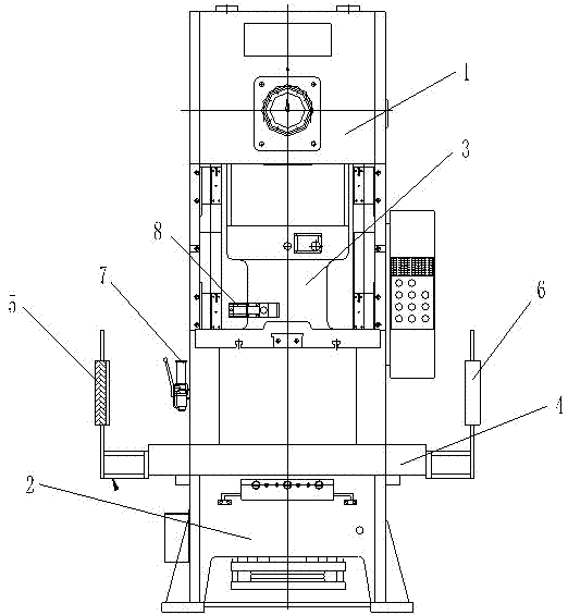
[0013] Such as figure 1 As shown, a punch press with a photoelectric protection device includes a punch press body 1, a punch lower body 2, a photoelectric protection device and an external control box 7, and a stamping slider 3 is arranged inside the punch press body 1, and a punch slide 3 is arranged inside the punch press body 1. Fuselage 2 is provided with workbench 4, and described stamping slide block 3 is positioned at workbench 4 tops, and faces workbench 4, is provided with external control box 7 on the side plate of one side of fuselage 1 on punching machine, so The photoelectric protection device includes a signal transmitting and receiving device 5 and a signal reflecting device 6 arranged on both sides of the workbench. The signal transmitting and receiving device 5 is located on the same side as the external control box 7 and is connected by a signal line...


PUM


Abstract

The invention discloses a punch press with a photoelectric protection device. The punch press comprises an upper body and a lower body, wherein a stamping slider is arranged in the upper body, a workbench is arranged on the lower body, and the stamping slider is located at the upper part of the workbench and is just opposite to the workbench. The punch press is characterized by further comprising a photoelectric protection device and an external control box, wherein the external control box is arranged on a side plate on one side of the upper body; the photoelectric protection device comprises a signal transmitting/receiving device and a signal reflecting device which are arranged on the two sides of the workbench; and the signal transmitting/receiving device and the external control box are located on the same side and connected through a signal wire. The invention solves the problems that the stamping protection device of the punch press is unreasonable, the protection effect is relatively bad and accidents often happen in the prior art. The invention provides a punch press with a photoelectric protection device, which is simple and practical in structure, can quickly stop the punching work and has relatively high reliability.

Description

[0001] technical field [0002] The invention discloses a punching machine, in particular to a punching machine with a photoelectric protection device. Background technique [0003] Punching machines are widely used in the field of machining. The punch press generally includes a fixed upper fuselage and a lower fuselage. The upper arm of the upper fuselage, the workbench of the lower fuselage and the vertical fuselage part connecting the upper fuselage and the lower fuselage are surrounded by the stamping parts of the punch press. The working space is the tiger’s mouth. On the upper arm of the upper body’s tiger’s mouth, there is a stamping slider that can reciprocate up and down. When stamping on the machine tool, a corresponding mold needs to be installed on the machine tool. The mold includes the upper ball screw and the die. The upper ball screw is connected to the stamping slider by thread, the die corresponding to the upper ball screw is fixed on the workbench, the wo...

Claims


Application Information

Patent Timeline
Patent Type & Authority Applications(China)
IPC IPC(8): B30B1/00B30B15/28F16P3/14
Inventor 黄逸仁
Owner 江苏人人发机器制造有限公司
Why Eureka
Try Eureka