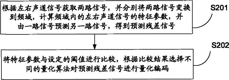
Quantization coding method and quantization coding device of prediction residual signal
A technology of prediction residual and quantization coding, applied in the field of signal processing, can solve problems such as limitations, and achieve the effect of good reconstruction quality
- Summary
- Abstract
- Description
- Claims
- Application Information
AI Technical Summary
Problems solved by technology
Method used
Image
Examples
example 1
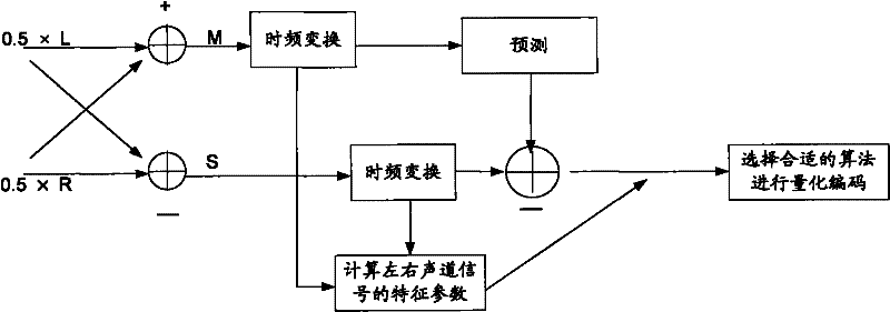
[0025] see Figure 4 , is a schematic diagram of Quantization Coding Example 1 of the prediction residual signal according to the embodiment of the present invention. The implementation process is described as follows:
[0026] (1) Downmix the left channel signal L and the right channel signal R to obtain two signals, namely the mono signal M and the sideband signal S:
[0027] M=(L+R) / 2; S=(L-R) / 2
[0028] (2) The mono signal M is decoded locally after passing through the mono encoder, and the decoded M signal is transformed into the frequency domain through MDCT (Modified Discrete Cosine Transform, improved discrete cosine transform); the sideband signal S is passed through the delay Afterwards, the MDCT transformation to the frequency domain is also carried out.
[0029] (3) Calculate the channel level difference of the left and right channel signals in the frequency domain according to the signal M and the signal S, specifically including the following substeps:
[003...
example 2
[0059] see Figure 5 , is a schematic diagram of Example 2 of quantization coding of the predicted residual signal according to the embodiment of the present invention. The main difference from Example 1 is that one of the two signals in Example 2 is a monophonic signal M, and the other is one of the left and right channel signals. In Example 2, the left channel signal L is taken as an example. The main process of its implementation is introduced as follows:
[0060] (1) The left channel signal L and the right channel signal R are mixed down to obtain a mono signal M: M=(L+R) / 2;
[0061] Determine the two signals as the signal M and the left channel signal L.
[0062] (2) The mono signal M is decoded locally after passing through the mono encoder, and the decoded M signal is transformed into the frequency domain through MDCT; after the left channel signal L is delayed, it is also transformed into the frequency domain through MDCT.
[0063] (3) Calculate the channel level di...
example 3
[0091] see Image 6 , is a schematic diagram of example 3 of quantization coding of the prediction residual signal according to the embodiment of the present invention, and its implementation process is introduced as follows:
[0092] (1) Downmix the left channel signal L and the right channel signal R to obtain two signals, namely the mono signal M and the sideband signal S:
[0093] M=(L+R) / 2; S=(L-R) / 2
[0094] (2) The mono signal M is decoded locally after passing through the mono encoder, and the decoded M signal is transformed into the frequency domain through MDCT; after the sideband signal S is delayed, it is also transformed into the frequency domain through MDCT.
[0095] (3) Using the frequency domain correlation prediction algorithm to obtain the prediction residual signal.
[0096] In this step, any frequency-domain correlation prediction algorithm can be used for calculation, and details will not be repeated here.
[0097] (4) Calculate the correlation value o...
PUM
 Abstract
Description
Claims
Application Information
 - R&D
- Intellectual Property
- Life Sciences
- Materials
- Tech Scout
- Unparalleled Data Quality
- Higher Quality Content
- 60% Fewer Hallucinations
Browse by: Latest US Patents, China's latest patents, Technical Efficacy Thesaurus, Application Domain, Technology Topic, Popular Technical Reports.
© 2025 PatSnap. All rights reserved.Legal|Privacy policy|Modern Slavery Act Transparency Statement|Sitemap|About US| Contact US: help@patsnap.com


