
Digital optical terminal with Base-mode Camera Link interface

A digital light and mode technology, applied in the field of video data transmission, can solve the problems of large capacity and high bandwidth video data transmission, small bandwidth and low data capacity that are not applicable to CameraLink video

Inactive Publication Date: 2011-11-16
CHANGCHUN INST OF OPTICS FINE MECHANICS & PHYSICS CHINESE ACAD OF SCI
View PDF3 Cites 15 Cited by
  • Summary
  • Abstract
  • Description
  • Claims
  • Application Information

AI Technical Summary

Problems solved by technology

The existing digital optical transceiver is a way of long-distance transmission of video data. Its technology is mature, but the existing digital optical transceiver has small bandwidth and low data capacity. It is mainly used in the field of analog video and is not suitable for the large capacity of Camera Link video. , High bandwidth video data transmission

Method used


Image

  • Digital optical terminal with Base-mode Camera Link interface
  • Digital optical terminal with Base-mode Camera Link interface
  • Digital optical terminal with Base-mode Camera Link interface

Examples


Embodiment Construction

[0012] The present invention will be described in further detail below in conjunction with the accompanying drawings and specific embodiments.

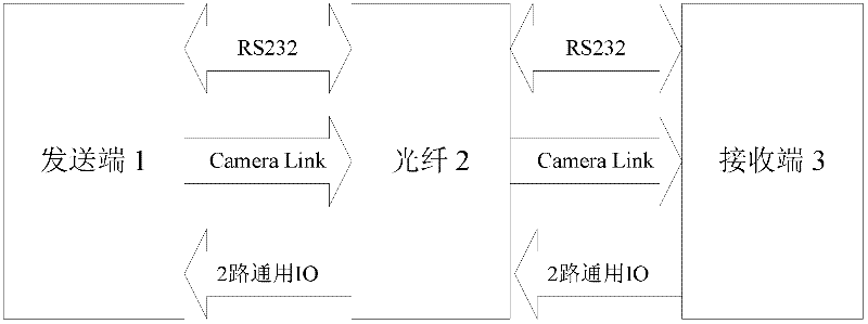
[0013] Such as figure 1 As shown, the digital optical transceiver with Base mode Camera Link interface of the present invention includes a sending end 1 , an optical fiber 2 and a receiving end 3 .

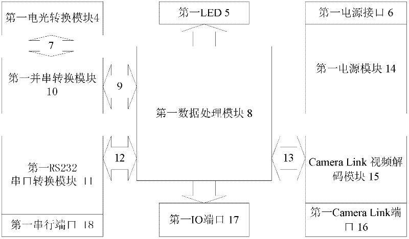
[0014] Such as figure 2 As shown, the sending end 1 includes a first electro-optical conversion module 4, a first LED 5, a first power interface 6, a first data processing module 8, a first parallel-to-serial conversion module 10, a first RS232 serial port conversion module 11, a first Power supply module 14, Camera Link video decoding module 15, the first Camera Link port 16, the first IO port 17 and the first serial port 18; Camera Link video decoding module 15 is mainly made of chip DS90CR288 and its peripheral circuit, the first Camera Link port 16 is composed of MDR26 connector, the first data processing module 8 is composed of FP...


PUM


Abstract

The invention provides a digital optical terminal with a Base-mode Camera Link interface, relating to the field of video data transmission. The optical terminal comprises a transmitting terminal and a receiving terminal which are communicated through an optical fiber. The transmitting terminal converts standard Base-mode Camera Link video data into optical signals, the optical signals are transmitted to the receiving terminal through the optical fiber, and the receiving terminal converts the optical signals into standard Base-mode Camera Link digital video signals and outputs the digital video signals. The transmitting terminal further converts a group of standard RS232 serial data into optical signals and transmits the optical signals to the receiving terminal. The receiving terminal converts the optical signals into a group of standard RS232 serial data and outputs the serial data. The receiving terminal further transmits a group of RS232 data back to the transmitting terminal according to above mode. At the same time, the receiving terminal transmits IO (input output) signals to the transmitting terminal by using the above electrical-to-optical conversion method, and the transmitting terminal outputs the IO signals. The digital optical terminal is applicable to long-distance transmission situations of Camera Link video.

Description

technical field [0001] The invention relates to the field of video data transmission, in particular to a digital optical transceiver with a Base mode Camera Link interface. Background technique [0002] The transmission rate of the Camera Link protocol can reach 2.83Gb / s, which is enough to meet the requirements of today's digital cameras for large data transmission rates. The link protocol has a short transmission distance, and its protocol stipulates that the transmission distance is only 10m, which is not suitable for the requirements of long-distance data transmission. The existing digital optical transceiver is a way of long-distance transmission of video data. Its technology is mature, but the existing digital optical transceiver has small bandwidth and low data capacity. It is mainly used in the analog video field and is not suitable for the large capacity of Camera Link video. , High-bandwidth video data transmission. Contents of the invention [0003] The purpos...

Claims


Application Information

Patent Timeline
IPC IPC(8): H04B10/14H04B10/40
Inventor 张岳阴玉梅杨晓霞吴庆林
Owner CHANGCHUN INST OF OPTICS FINE MECHANICS & PHYSICS CHINESE ACAD OF SCI
Learn More