
Lock-on switch system for hand drill and hand drill having the same

A technology for locking switches and switches, which is applied in the direction of electric switches, manufacturing tools, striking tools, etc., can solve the problems of low locking reliability, large cumulative tolerance, and inaccurately limited locking size, etc., so as to reduce development time and Processing cost, effect of reducing tolerance chain

Inactive Publication Date: 2011-11-16
BOSCH POWER TOOLS CHINA
View PDF6 Cites 12 Cited by
  • Summary
  • Abstract
  • Description
  • Claims
  • Application Information

AI Technical Summary

Problems solved by technology

Therefore, the locking reliability is lower
Moreover, there are too many tolerance chains in this switch construction, so that the cumulative tolerances are very large and the locking dimensions cannot be precisely defined

Method used


Image

  • Lock-on switch system for hand drill and hand drill having the same
  • Lock-on switch system for hand drill and hand drill having the same
  • Lock-on switch system for hand drill and hand drill having the same

Examples


Embodiment Construction

[0028] Now, preferred embodiments of a lock switch system for a hand drill and a hand drill having such a lock switch system of the present invention will be described with reference to the accompanying drawings.

[0029] Figure 4 and 5 A switch system for a hand drill according to an embodiment of the invention is shown. The switch system includes a switch (not shown) provided in a switch housing 3 for controlling the operation of the hand drill. A switch is arranged in the upper part of the handle of the hand drill and can be actuated by the user via a trigger 2 arranged in front of the switch and movable horizontally between a starting position and a pushed-in position. That is, the trigger can be pushed toward the switch to the pushed position, thereby actuating the switch. The trigger 2 can be locked in the pushed position by a locking mechanism when the pushing force applied to the trigger is released. The trigger 2 can also be unlocked from the pushed-in position a...


PUM


Abstract

A lock-on switch system for hand drill comprises: a switch disposed in a switch housing(3) for controlling the operation of the drill; a trigger(2) which is adapted to be movable between a home position where the trigger(2) turns off the switch and a pushed-in position where the trigger(2) turns on the switch; a pivotable locking bar(4) having a front end adapted to be engaged with the trigger(2) for locking the trigger(2) in the pushed-in position; a slidable actuator(7) adapted for pushing the locking bar(4) into engagement with the trigger(2); and biasing means adapted for applying a force on the locking bar(4) in a direction of disengaging the locking bar(4) from the trigger(2).

Description

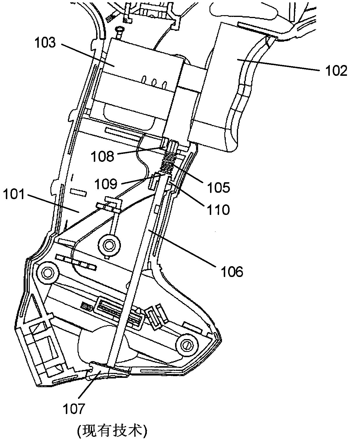
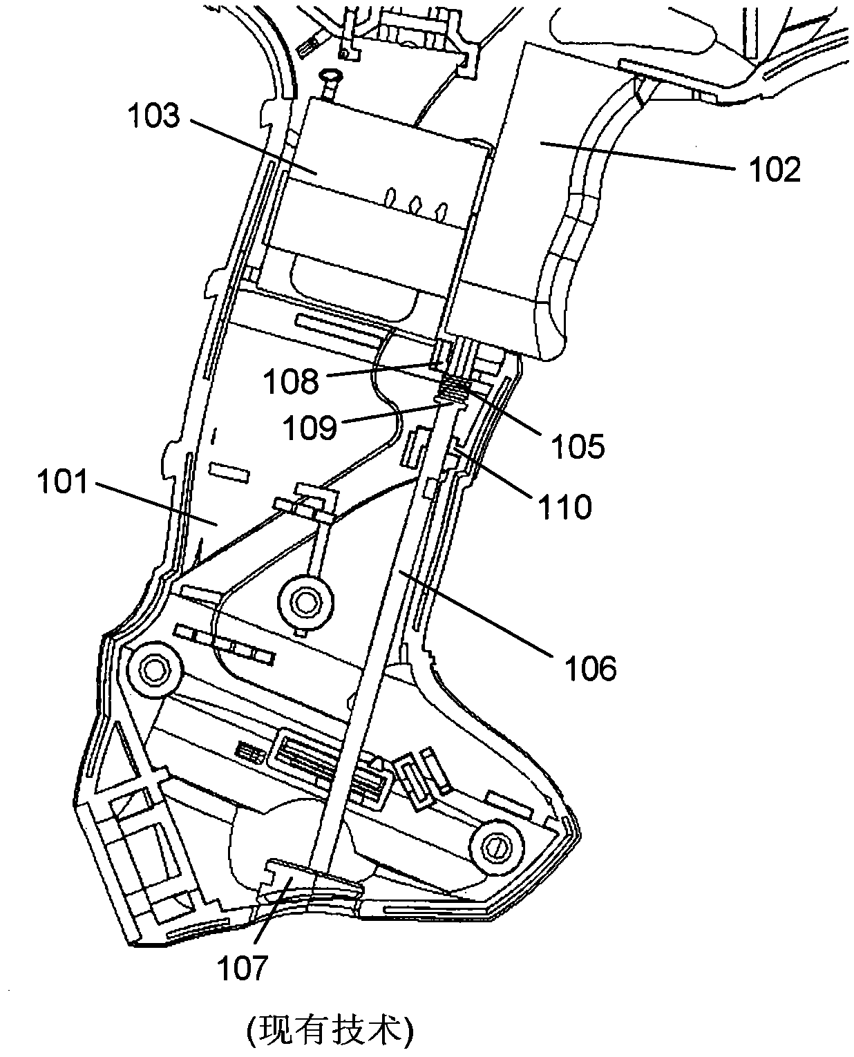
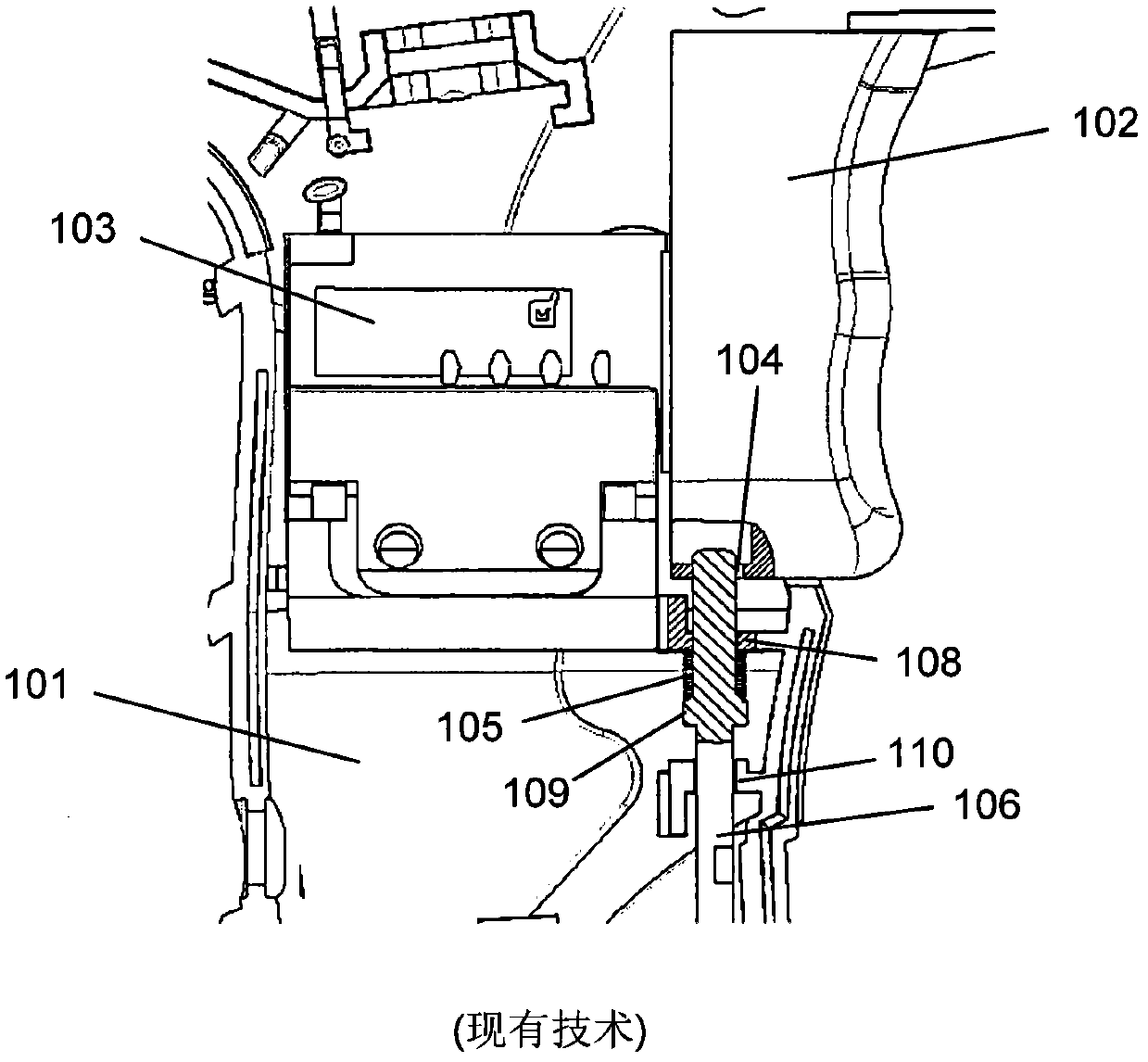
technical field [0001] The invention relates to a locking switch system for a hand drill and a hand drill with such a locking switch system. Background technique [0002] A hand drill generally has a switch mounted within the housing of the hand drill for controlling the operation of the hand drill. The switch is actuatable by a user via a trigger which can be locked in an activated position by a locking mechanism. Figures 1 to 3 Such a switch is shown. As shown in these figures, the switch is housed in a switch housing 103 within the handle 101 of the hand drill. The switch is connected to a trigger 102 which is movable between a starting position and a pushed-in position. That is, the trigger can be pushed inward toward the switch, thereby actuating the switch. A return means pushes the trigger back in a direction towards its original position. A locking actuator 106 is provided to maintain the trigger in its pushed in position. A rod-shaped actuator extends in a dir...

Claims


Application Information

Patent Timeline
Patent Type & Authority Applications(China)
IPC IPC(8): B25F5/00B25D17/04H01H13/02
CPCB25D2250/261H01H3/20H01H9/061B25F5/00B25F5/02
Inventor 时雪冬蒋贤斌J·维克
Owner BOSCH POWER TOOLS CHINA
Learn More