Transverse control arm of a motor vehicle

A technology of transverse linkages and vehicles, applied in the direction of vehicle components, cantilever mounted on pivots, elastic suspensions, etc., can solve the problems of journal joint damage, impossible to eliminate, etc.

Active Publication Date: 2011-11-16
FORD GERMANY
View PDF11 Cites 9 Cited by
  • Summary
  • Abstract
  • Description
  • Claims
  • Application Information

AI Technical Summary

Problems solved by technology

However, it is impossible to dispel this impression since the journal connections or journals are likely to have actually been destroyed prior to the collision
On the other hand, however, a collision between the wheel and the curb given as an example can also lead to the destruction of the journal connection or the journal

Method used


Image

  • Transverse control arm of a motor vehicle
  • Transverse control arm of a motor vehicle
  • Transverse control arm of a motor vehicle

Examples


Embodiment Construction

[0052] In the various figures, identical parts are always provided with the same reference signs, for which reason they are also generally described only once.

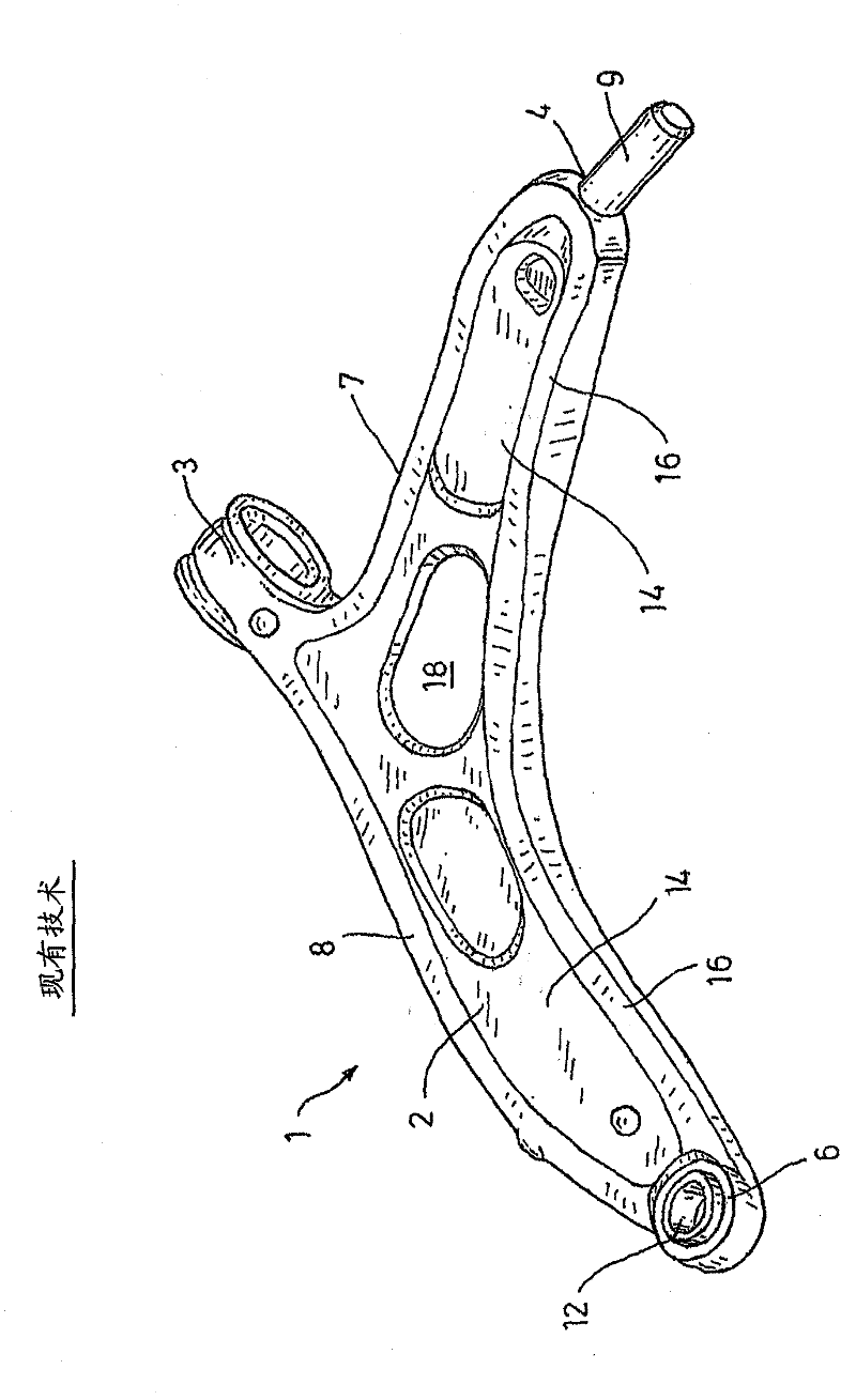
[0053] figure 1 A transverse link 1 according to the prior art is shown. The transverse link 1 has a main body 2 with a first fixing area 3 and a second fixing area 4 for pivotal attachment to a vehicle frame element (not shown, eg a subframe). The transverse link 1 also has a further fixing area, namely a third fixing area 6 , for pivotal attachment to a hub carrier (not shown). The main body 2 with the frame wings 7 and the wheel wings 8 is substantially L-shaped. The first fastening area 3 and the second fastening area 4 are arranged on a frame wing 7 . The first fastening area 3 is realized, for example, as a sleeve, the second fastening area 4 is realized, for example, by a bearing element 11 (see Figure 4 ) around the journal 9.

[0054] The third fastening area 6 is arranged on the wheel wing 8 and is for...


PUM


Abstract

The invention relates to a transverse control arm (1), having a main body (2) which comprises at least one first fastening region (3) for coupling to a vehicle frame element and at least one further fastening region (6) for coupling to a wheel carrier, wherein the main body (2) comprises at least one wheel limb (8). In order to largely prevent destruction of the joggle joint of the transverse control arm to a wheel carrier when the wheel, for example, hits a curb, it is proposed to provide a transition region (19), which is disposed between the wheel limb (8) and the further fastening region (6), and wherein the transition region (19) is designed such that a shape-change or deformation zone (21) is formed, which acts in the longitudinal direction (Y) of the wheel limb (8).

Description

technical field [0001] The invention relates to a transverse link having a body having at least one first fixing region for pivotal attachment to a vehicle frame element and for pivotal attachment to a wheel carrier (hub carrier) at least one other fastening area, said main body has at least one wheel wing (wheel limb). Background technique [0002] EP1167092B1 already discloses a transverse link for the wheel suspension of a motor vehicle wheel, said link comprising a one-piece casting with three fastening areas. Two fastening areas are used to fasten the transverse link to the chassis. The third fixation area is for the bearing assembly that is pivotally attached to the wheel. Furthermore, in order to implement a transverse link in consideration of vehicle safety, EP1167092B1 proposes that at least one hole or three holes should be provided in a flat area. A bevel of increasing material thickness is provided in one of the holes. In order to achieve a transverse link th...

Claims


Application Information

Patent Timeline
Patent Type & Authority Applications(China)
IPC IPC(8): B60G7/00B60G3/00
CPCB60G2206/122B60G7/001B60G2206/8101B60G2200/1424B60G2204/41B60G2206/7102B60G2206/016B60G2204/416B60G2204/143B60G2204/148
Inventor 托马斯·格哈德斯迈克尔·约翰内斯·弗兰岑马克·赛门沃尔夫冈·大卫马丁娜·拜尔延斯·沃勒特法兰克·舍珀卡斯坦·克洛斯特迈尔卡斯坦·桑德
Owner FORD GERMANY
Why Eureka
Try Eureka