A cooling system for a combustion engine

A technology of cooling system and internal combustion engine, applied in the direction of engine cooling, mechanical equipment, engine components, etc., can solve the problems of complex assembly, longitudinal gap, inaccurate alignment, etc.

Inactive Publication Date: 2011-11-16
ILLINOIS TOOL WORKS INC
View PDF5 Cites 0 Cited by
  • Summary
  • Abstract
  • Description
  • Claims
  • Application Information

AI Technical Summary

Problems solved by technology

However, this technique has the disadvantage that if a single part fails, the entire subassembly has to be replaced as a whole
Prone to misalignment and longitudinal play

Method used


Image

  • A cooling system for a combustion engine
  • A cooling system for a combustion engine
  • A cooling system for a combustion engine

Examples


Embodiment Construction

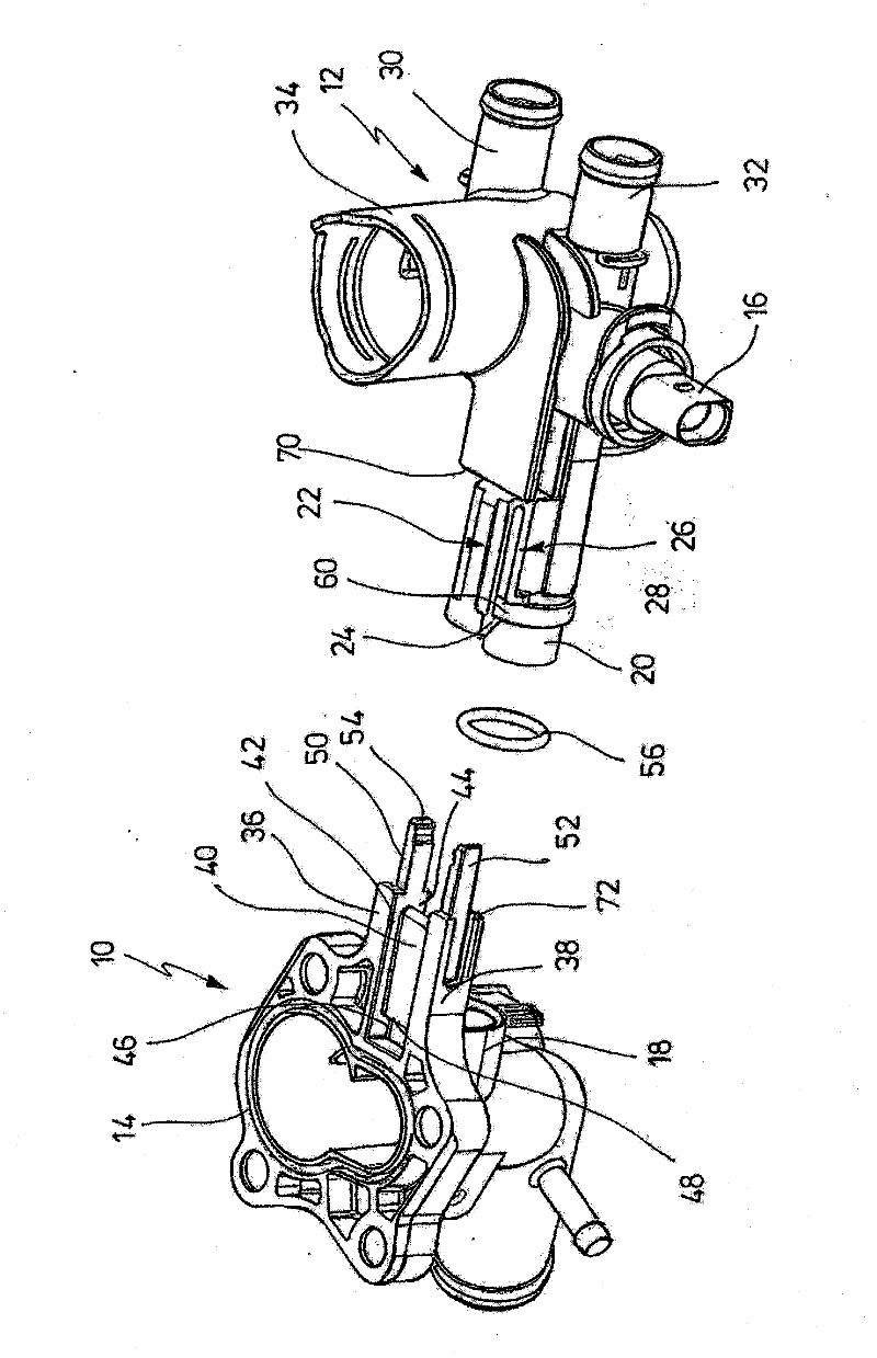
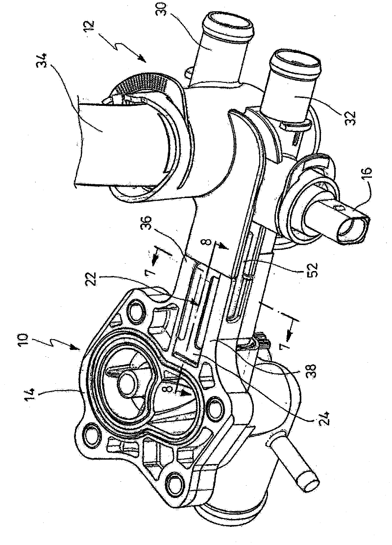
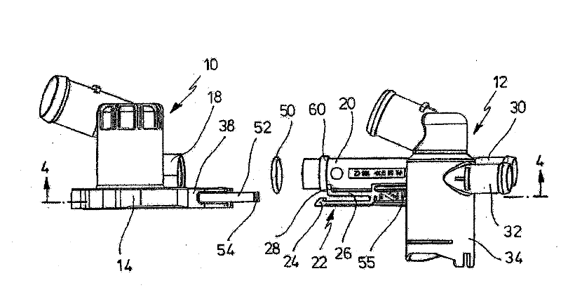
[0019] figure 1 Shown are a first subcomponent 10 and a second subcomponent 12 in a refrigerant circuit (not shown in detail) of a cooling system of an internal combustion engine. As shown, subassembly 10 is a thermostatic valve. The subassembly 10 is secured to the omitted engine section by a flange. The subassembly 10 is tightly secured by flanges 14 to the omitted engine section. As shown, the sub-component 12 is a cooling water regulator equipped with a stub 16 allowing connection to a rotary drive. The two subcomponents 10 and 12 should be connected to each other as a flow connection. This (fluid) connection should be effective when the subassembly 10 is fastened to the internal combustion engine. The subcomponent 10 comprises a pipe section 18 into which a pipe section 20 of the subcomponent 12 can be inserted. The design of the subcomponents will be clarified below. A resilient shank 22 integral with the subassembly 12 extends over, spaced from, and parallel to th...


PUM


Abstract

A cooling system for a combustion engine comprises a coolant circuit, further a first sub-assembly configured in said circuit and fitted with a first pipe segment and a second sub-assembly in said circuit fitted with at least one second pipe segment, further a sealed connection between the pipe segments, either the first or the second sub-assembly being fitted with means for solidly joining it to said engine, characterized in that the pipe segments of the two sub-assemblies can be plugged into one another and are displaceable relative to each other, a seal being configured between them, in that furthermore a resilient locking tang running parallel to the axis of the first pipe segment of the first subassembly is integral with said first sub-assembly and is fitted at its free end with a detent element pointing toward the pipe segment, that an elongated guide portion running parallel to and spaced from the locking tang between the pipe segment and the locking tang is integral with the first sub-assembly.

Description

technical field [0001] The present invention relates to a cooling system for an internal combustion engine as stated in claim 1 . Background technique [0002] It is known to design cooling water regulators for cooling systems of internal combustion engines, which have two subcomponents, one of which includes, for example, a temperature control valve. It is also known that the housings of such subcomponents, which are mostly made of plastic, are produced in one piece. However, this technique has the disadvantage that if a single part fails, the entire subassembly has to be replaced as a whole. This disadvantage wastes material and requires fine workmanship. [0003] It is also known that the aforementioned subcomponents are manufactured separately. Usually one of the subassemblies, the thermostat subassembly, is rigidly coupled to the internal combustion engine. Misalignment and longitudinal play are prone to occur when assembling this subassembly to another. Said assem...

Claims


Application Information

Patent Timeline
IPC IPC(8): F16L37/04
CPCF28F27/02F28F9/0258F28F9/0251F01P11/04F16L37/098
Inventor 罗尔夫・哈伯曼
Owner ILLINOIS TOOL WORKS INC
Why Eureka
Try Eureka