
Device for a system components of a high-voltage impulse test system

An inspection system, high-voltage pulse technology, applied in the direction of testing dielectric strength, testing circuits, etc., can solve the problems of time-consuming and inconvenient operation, and achieve the effect of shortening installation time, reducing land occupation requirements, and simple transportability

Active Publication Date: 2011-11-16
MASCHFAB REINHAUSEN GEBR SCHEUBECK GMBH & CO KG
View PDF5 Cites 0 Cited by
  • Summary
  • Abstract
  • Description
  • Claims
  • Application Information

AI Technical Summary

Problems solved by technology

This process is time-consuming and inconvenient

Method used


Image

  • Device for a system components of a high-voltage impulse test system
  • Device for a system components of a high-voltage impulse test system
  • Device for a system components of a high-voltage impulse test system

Examples


Embodiment Construction

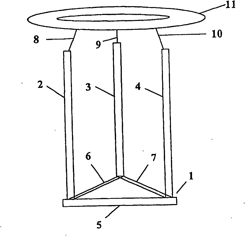
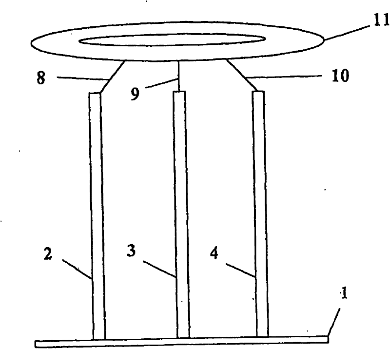
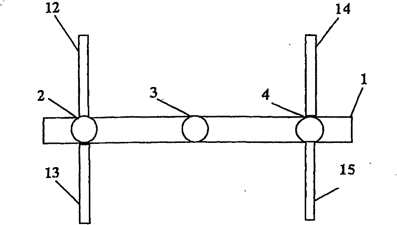
[0021] figure 1 A main frame 1 according to the invention is shown for accommodating auxiliary components such as a cut-off spark gap 2 , a voltage divider 3 or an overshoot compensation component 4 . accessories in figure 1 is only shown schematically for reasons of overview. The main frame 1 is securely upright in this respect and has, for example, a triangular base region consisting of interconnected steel tubes 5 , 6 and 7 . The cut-off spark gap 2, the voltage divider 3 and the overshoot compensating component 4 are arranged on respective corners of the main frame 1 and electrically connected thereto. Furthermore, the upper ends of the respective auxiliary parts are mechanically fixed by means of electrically conductive crossbars 8 , 9 and 10 . Connected to the horizontal frames 8, 9 and 10 are the top electrodes 11, which can be formed as rings, for example. The conductive crossbars 8 , 9 and 10 thus both fulfill the task of mechanically holding the tip electrode 11 ...


PUM


Abstract

The present invention relates to a device for system components of a high-voltage impulse test system, preferably for quality assurance of power transformers. According to the invention, a common base frame having only one main electrode common to the system components is proposed for the spatial collection of the system components.

Description

technical field [0001] The present invention relates to an arrangement of system components of a high voltage pulse inspection system preferably used for quality assurance of power transformers. Background technique [0002] The purpose of the high-voltage test is to simulate transient overvoltages in a three-phase grid with the aid of artificially generated impulse impulses. In this respect, a distinction is conventionally made between external overvoltages, for example caused by lightning strikes, and internal circuit overvoltages due to switching processes within the grid. A large number of overvoltage phenomena are reduced to standardized lightning impulse and circuit impulse voltages for inspection purposes. For these test voltages, characteristic parameters describing the voltage rise, peak and drop within a defined tolerance are determined. When it is necessary to simulate the cut-off lightning impulse voltage affected by very rapid voltage changes, the cut-off effe...

Claims


Application Information

Patent Timeline
Patent Type & Authority Applications(China)
IPC IPC(8): G01R31/14
CPCG01R31/14
Inventor M·希努M·库巴特T·施泰纳
Owner MASCHFAB REINHAUSEN GEBR SCHEUBECK GMBH & CO KG
Learn More