Permanent magnet type rotary electrical machine
A rotating electric machine, permanent magnet technology, applied in the field of permanent magnet electric rotating machine and its manufacturing, can solve the problems of output and efficiency reduction of permanent magnet electric rotating machine, achieve suppression increase, realize efficiency, and suppress increase of magnetizing current Effect
- Summary
- Abstract
- Description
- Claims
- Application Information
AI Technical Summary
Problems solved by technology
Method used
Image

Examples
Embodiment 1
[0073] (1-1) Structure
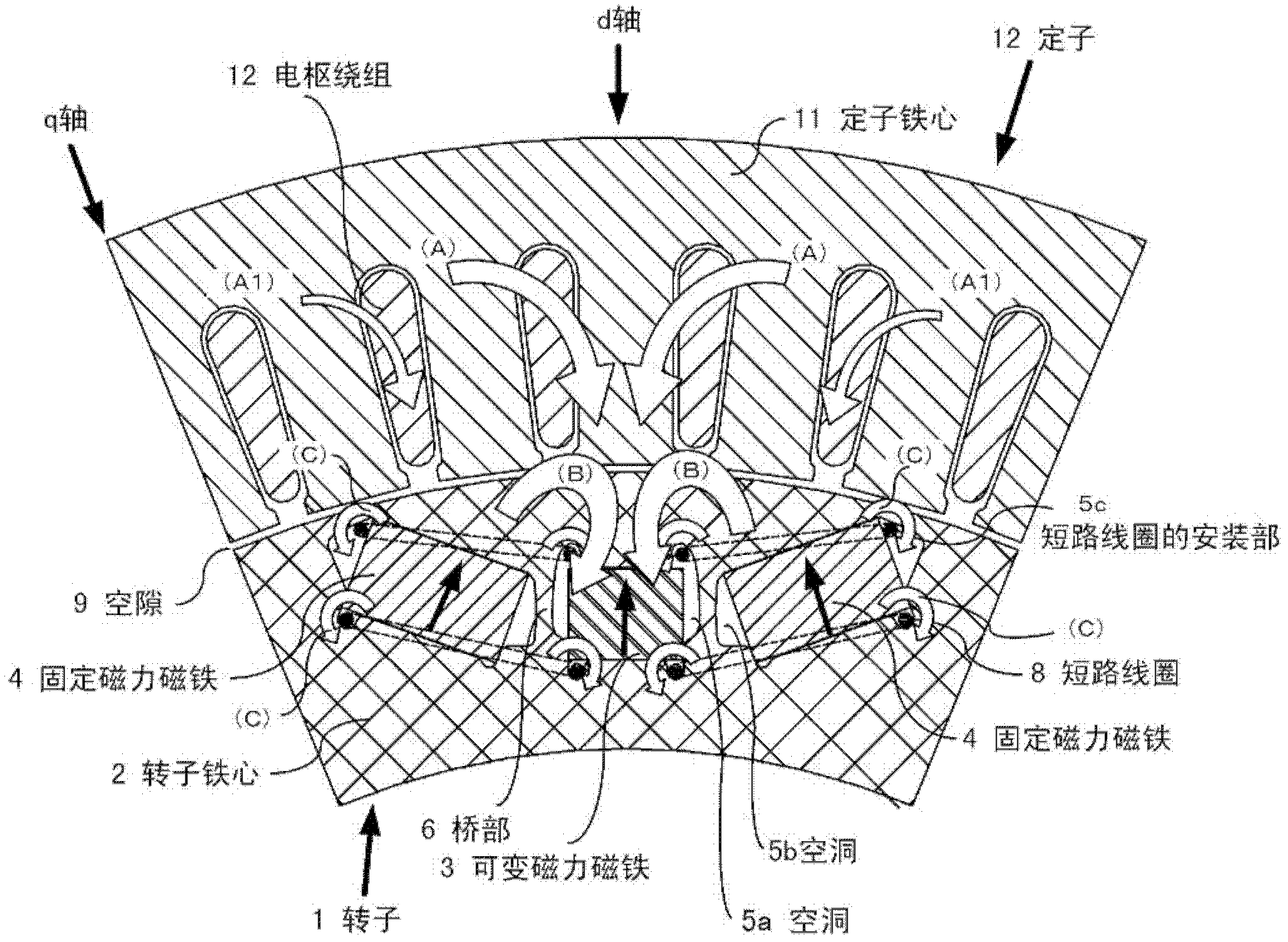
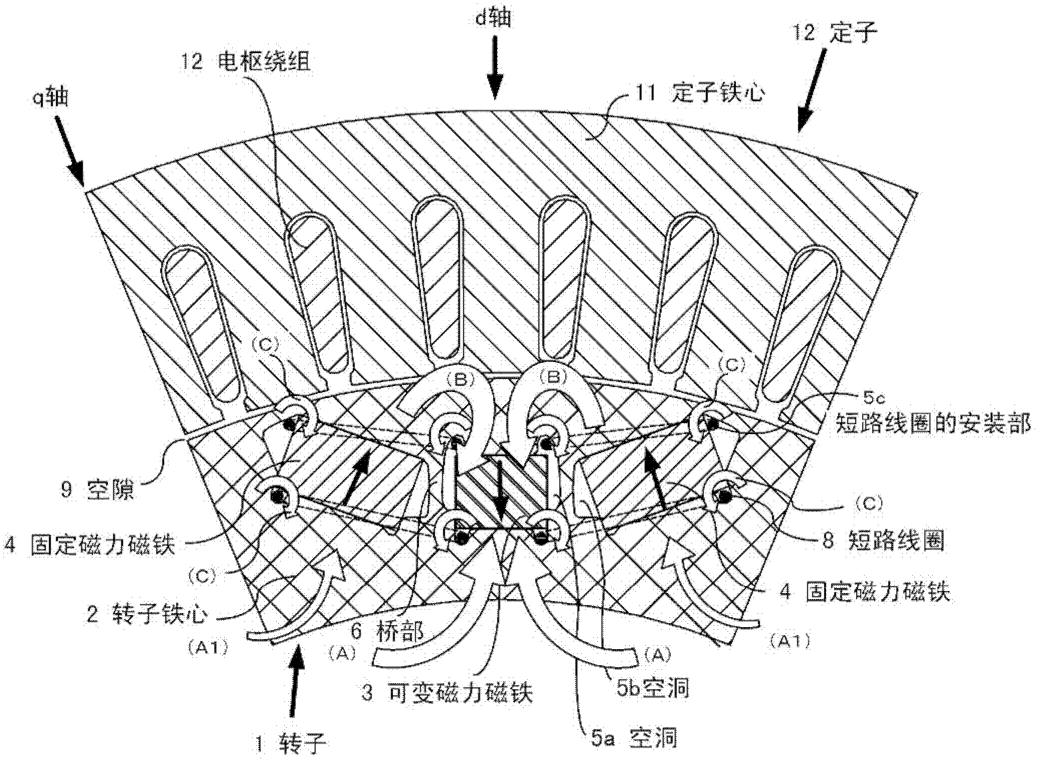
[0074] use figure 1 with 2 The first embodiment of the first invention will be described. figure 1 It is a cross-sectional view of the permanent magnet type rotating electrical machine of this embodiment in a direction orthogonal to the rotating shaft, and is a diagram showing the direction of magnetic flux during demagnetization, figure 2 It is a diagram showing the direction of magnetic flux during the same increase in magnetization.
[0075] Such as figure 1 As shown, the rotor 1 of Embodiment 1 of the first invention includes: a rotor core 2; a permanent magnet 3 (hereinafter referred to as a variable magnetic force magnet) having a small product of the coercive force and the thickness of the magnetization direction; and the coercive force and the magnetization direction Permanent magnets (hereinafter referred to as fixed magnetic magnets) 4 and 4 having a large product of thickness. The rotor core 2 is formed by laminating silicon steel sheets, and th...
Embodiment 2
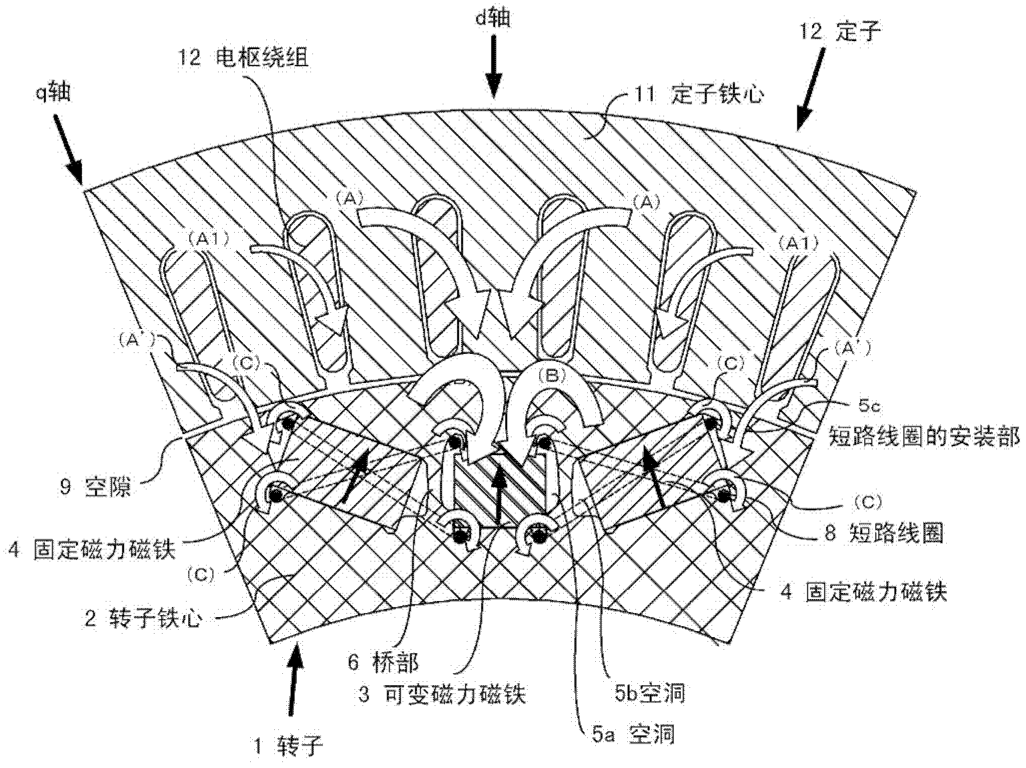
[0103] In the second embodiment, the short-circuit coil 8 is provided parallel to the upper and lower surfaces (direction perpendicular to the magnetization direction) of the fixed magnetic magnet, but it can also be image 3 , 4 As shown, one is provided in the diagonal direction of the short-circuit coil, or two are provided in an X shape. That is, the fixed magnetic force magnet 4 is arranged in a direction that maintains a certain angle with respect to the magnetization direction of the fixed magnetic force magnet 4, and is arranged at the diagonal of the cross section in the direction orthogonal to the axial direction of the rotor of the fixed magnetic force magnet 4. At this time, the short-circuit coil 8 may be arranged in close contact with the fixed magnetic magnet 4. It is also possible to extend one end of the short-circuit coil 8 to the periphery of the variable magnetic force magnet 3, and the fixed magnetic force magnet 4 and the bridge 6 are included inside the sh...
Embodiment 3
[0108] The first invention is not limited to the above-mentioned embodiments, but also includes the following embodiment 3.
[0109] (1) In each of the above-mentioned embodiments, a 4-pole rotating electric machine is shown, but the first invention can of course be applied to a multi-pole rotating electric machine such as 8-pole. Depending on the number of poles, the arrangement position and shape of the permanent magnet will of course have some changes, but the same effect and effect can be obtained. In particular, in each of the above embodiments, a variable magnetic force magnet is arranged in the center and a fixed magnetic force magnet is arranged on both sides thereof, but other arrangements of variable magnetic force magnets and fixed magnetic force magnets may also be applied.
[0110] (2) In the rotor core 2 described above, the shape or position of the cavity provided to form a magnetic shield on the outer peripheral side of the fixed magnetic magnet, and the inner perip...
PUM
 Abstract
Description
Claims
Application Information
 - R&D Engineer
- R&D Manager
- IP Professional
- Industry Leading Data Capabilities
- Powerful AI technology
- Patent DNA Extraction
Browse by: Latest US Patents, China's latest patents, Technical Efficacy Thesaurus, Application Domain, Technology Topic.
© 2024 PatSnap. All rights reserved.Legal|Privacy policy|Modern Slavery Act Transparency Statement|Sitemap