Permanent magnet type rotating electric machine

A technology of permanent magnets and rotating motors, applied in the direction of magnetic circuit rotating parts, magnetic circuit shape/style/structure, magnetic circuit, etc., can solve problems such as deterioration of comprehensive operating efficiency, and achieve the effect of realizing efficiency

Active Publication Date: 2011-10-12
KK TOSHIBA
View PDF5 Cites 25 Cited by
  • Summary
  • Abstract
  • Description
  • Claims
  • Application Information

AI Technical Summary

Problems solved by technology

In this case, since the motor only generates losses, the overall operating efficiency deteriorates

Method used


Image

  • Permanent magnet type rotating electric machine
  • Permanent magnet type rotating electric machine
  • Permanent magnet type rotating electric machine

Examples


Embodiment Construction

[0053] (1. The first embodiment)

[0054] (1-1. Composition)

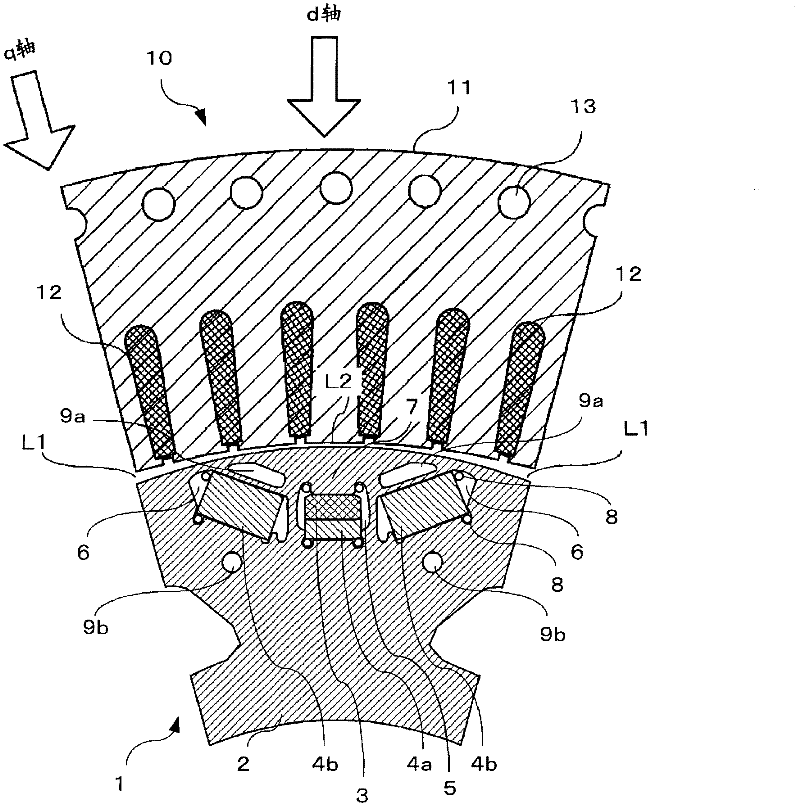
[0055] use figure 1 The first embodiment of the present invention will be described.

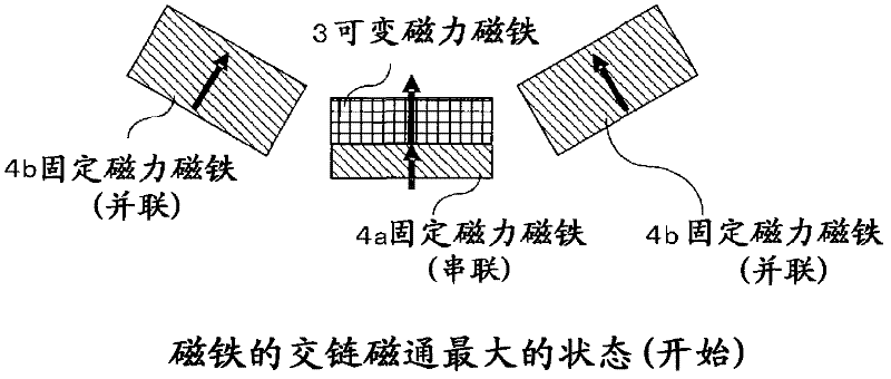
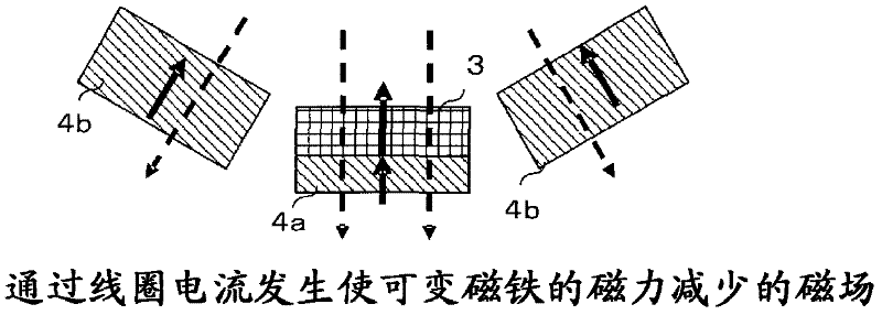
[0056] The rotor 1 of the first embodiment of the present invention consists of figure 1 As shown, the rotor core 2, the permanent magnet 3 having a small product of the coercive force and the thickness in the magnetization direction (hereinafter, referred to as a variable magnetic force magnet), and the permanent magnet having a large product of the coercive force and the thickness of the magnetization direction (hereinafter, Be called fixed magnetic force magnet) 4a, 4b constitute. Here, 4a indicates one fixed magnetic force magnet arranged in series with the variable magnetic force magnet 3 on the magnetic circuit, and 4b indicates two fixed magnetic force magnets arranged in parallel with the variable magnetic force magnet 3 on the magnetic circuit. The rotor core 2 is formed by laminating silicon steel plates, and th...


PUM


Abstract

This permanent magnet type rotating electric machine suppresses an increase in the magnetizing current during demagnetization and during magnetization, and enables variable speed operation over a wide range from low speed to high speed with high output. A rotor (1) is comprised of a rotor core (2), a variable magnetic force magnet (3), and a fixed magnetic force magnet (4). The variable magnetic force magnet (3) and a fixed magnetic force magnet (4a) overlap in the magnetization direction thereof to form a magnet series. This magnet series is disposed within the rotor core (2) at a position whereby the direction of magnetization is in the direction of axis d. On either side of the magnetic series of the variable magnetic force magnet (3) and the fixed magnetic force magnet (4a), fixed magnetic force magnets (4b, 4b) are disposed at a position whereby the direction of magnetization is in the direction of axis d. When the interlinkage magnetic flux of the variable magnetic force magnet (3) is reduced, a magnetic field is activated in the reverse direction of the magnetization direction of the variable magnetic force magnet (3) by means of the armature winding current. When the interlinkage magnetic flux of the variable magnetic force magnet (3) is increased, a magnetic field is activated in the same direction as the magnetization direction of the magnet by means of the armature winding current.

Description

technical field [0001] The present invention relates to a permanent magnet type rotating electric machine which uses two or more permanent magnets, irreversibly changes the magnetic flux of at least one of them, and is capable of variable speed operation in a wide range from low speed to high speed. Background technique [0002] In general, permanent magnet type rotating electrical machines are roughly classified into two types. That is, a surface magnet type permanent magnet type rotating electrical machine in which a permanent magnet is attached to the outer periphery of a rotor core, and an embedded permanent magnet type rotating electrical machine in which a permanent magnet is embedded in a rotor core. As a motor for variable speed drive, an embedded permanent magnet type rotating electrical machine is applied. [0003] In a permanent magnet type rotating electrical machine, since the interlinkage flux of the permanent magnets is always generated at a constant strength...

Claims


Application Information

Patent Timeline
Patent Type & Authority Applications(China)
IPC IPC(8): H02K1/27
CPCH02K1/2766
Inventor 堺和人桥场丰高桥则雄结城和明
Owner KK TOSHIBA
Why Eureka
Try Eureka