
Vacuum glass with mounting holes

A technology of vacuum glass and installation holes, which is applied in the improvement of windows/doors, climate change adaptation, windows/doors, etc., can solve the problems of increasing the use cost of vacuum glass components, restricting the installation form of vacuum glass components, and reducing the efficiency of vacuum glass. , to reduce the thermal bridge effect, ensure the sound insulation effect, and achieve the effect of easy connection

Active Publication Date: 2011-11-23
洛阳兰迪真空玻璃科技有限公司
View PDF5 Cites 62 Cited by
  • Summary
  • Abstract
  • Description
  • Claims
  • Application Information

AI Technical Summary

Problems solved by technology

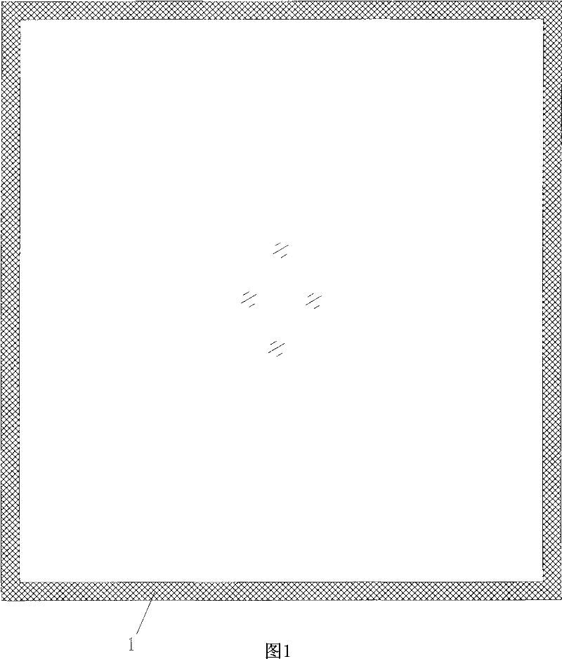
[0002] As a glass component with good heat insulation and sound insulation functions, vacuum glass has attracted more and more attention from people, but most of the previous research is basic research, and the relevant research results are more reflected in the principle structure of vacuum glass , the formation method of vacuum, and the sealing method of vacuum glass, etc., and is limited by the principle of vacuum glass formation, the structure of the proposed vacuum glass component is similar to that of common hollow glass components, such as figure 1 As shown in , when the vacuum glass with this structure is used later, it must be installed with a frame, and a frame with a bridge-breaking heat insulation structure must also be used, otherwise the efficiency of the vacuum glass will be greatly reduced, which will not only greatly increase The use cost of vacuum glass components also restricts the installation form of vacuum glass components

Method used


Image

  • Vacuum glass with mounting holes
  • Vacuum glass with mounting holes
  • Vacuum glass with mounting holes

Examples


Embodiment Construction

[0027] The present invention will be described in detail below in conjunction with the accompanying drawings.

[0028] exist figure 2 In the shown embodiment 1, the vacuum glass is composed of the lower glass plate 2 and the upper glass plate 3, and the sealing edge 1 near the edge of the upper and lower glass plates 2 and 3 is made of metal solidified on the surface of the glass plate. The metalized layer 6 and the metal sealing sheet 7 with a U-shaped cross-section are formed. Both sides of the metal sealing sheet 7 and the metallized layer 6 on the upper and lower glass plates are airtightly welded and connected by a metal brazing process. The hole 8 is arranged outside the sealing edge 1 , and the installation hole 8 is isolated from the vacuum space 5 by the sealing edge 1 .

[0029] The metallized layer 6 is consolidated on the surface of the glass plate to be sealed. The metallized layer 6 is sintered on the surface of the glass plate through a sintering process. The ...


PUM


Abstract

The invention discloses a vacuum glass with mounting holes, which is compounded from two or multiple glass plates, wherein the peripheries of two or multiple glass plates are mutually sealed hermetically by sealing edges; adjacent glass plates on the inner sides of the sealing edges are vacuumized; the vacuum glass is also provided with mounting holes; and the mounting holes penetrate through thetwo or multiple glass plates and are isolated from vacuum space on the vacuum glass. Since the vacuum glass is provided with the mounting holes, the vacuum glass can be installed and fixed after connecting pieces penetrate through the mounting holes, therefore a high-cost border is not used any more, convenience is brought for the installation of the vacuum glass, and the vacuum glass can be fixed more flexibly. In addition, a plurality of connecting pieces are used for fixing the vacuum glass, so that the section of a metal piece penetrating through the vacuum glass is greatly reduced, heat bridge effect is effectively lowered, and the heat insulation and sound-proof effects of the vacuum glass can be guaranteed. In addition, connecting pieces with the broken bridge heat insulation structure are easy to use, and cost is lower.

Description

technical field [0001] The invention relates to a vacuum glass, in particular to a vacuum glass with installation holes. Background technique [0002] As a glass component with good heat insulation and sound insulation functions, vacuum glass has attracted more and more attention from people, but most of the previous research is basic research, and the relevant research results are more reflected in the principle structure of vacuum glass , the formation method of vacuum, and the sealing method of vacuum glass, etc., and is limited by the principle of vacuum glass formation, the structure of the proposed vacuum glass component is similar to that of common hollow glass components, such as figure 1 As shown in , when the vacuum glass with this structure is used later, it must be installed with a frame, and a frame with a bridge-breaking heat insulation structure must also be used, otherwise the efficiency of the vacuum glass will be greatly reduced, which will not only greatly...

Claims


Application Information

Patent Timeline
IPC IPC(8): C03C27/08
CPCE06B3/5436Y02B80/24E06B3/6612Y02A30/249Y02B80/22
Inventor 赵雁李彦兵王章生
Owner 洛阳兰迪真空玻璃科技有限公司
Learn More