Eave connecting part, building framework structure and mounting method

A frame structure and connector technology, applied in the field of eaves connectors, can solve the problems of inability to realize fasteners, damage to ecology, and weak connections.

Inactive Publication Date: 2013-05-29
杨东佐
View PDF7 Cites 0 Cited by
  • Summary
  • Abstract
  • Description
  • Claims
  • Application Information

AI Technical Summary

Problems solved by technology

[0002] Existing steel structures of houses, frame steel structures of pavilions and other eaves, one is to weld the end face of one beam to the side of another beam, or to weld the end faces of two beams together. The force of the method is poor, and the construction is difficult; one is to fix the ends of the two beams together with non-inserted connectors by means of fasteners or welding. This connection method, the gravity of the beam and the support on the beam The gravity of the plate, etc. is finally concentrated on the fastener or the joint position of the weld, and the stress is excessively concentrated on the connection position between the beam and the beam, so that the connection position is poorly stressed and the connection is fragile; if no additional connection is used Fasteners cannot be realized because the end face of one beam needs to be fixed to the side of another beam; one is that building materials such as cement and wood need to be used, which destroys the ecology; during building demolition, building materials cannot be reused, Cause waste of resources and produce a large amount of construction waste that is difficult to handle

Method used


Image

  • Eave connecting part, building framework structure and mounting method
  • Eave connecting part, building framework structure and mounting method
  • Eave connecting part, building framework structure and mounting method

Examples


Embodiment 1

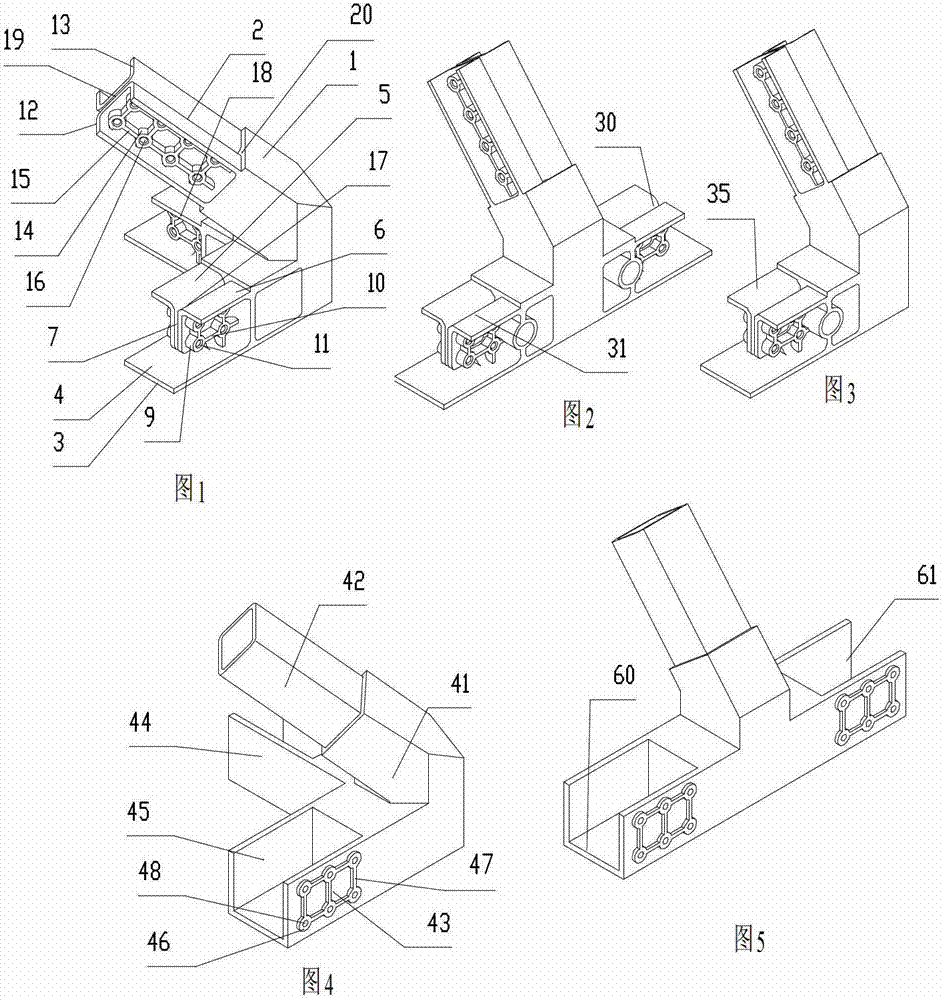
[0081] Such as figure 1 As shown, an eaves connector of a building frame structure includes an integrally formed eaves connector body 1, a beam plug joint 2 that is inserted into the end of a connecting beam that matches with it and protrudes obliquely upwards from the eaves connector body 1, two The ends of the side beams parallel to the horizontal plane, the side beam support joints 17 and the side beam support joints 18 perpendicular to each other are supported.

[0082]The side beam support joint 17 and the side beam support joint 18 all include side protrusions 3 extending vertically from the side of the eaves connector body 1, and the top surface 4 of the side protrusions 3 is the horizontal plane of the support side beam directly supporting the side beam; The top surface 4 of the side convex part 3 extends vertically upwards and then bends outwards. There are two symmetrical, horizontally juxtaposed limiting convex parts 5 and 6, and between the limiting convex parts 5 ...

Embodiment 2

[0086] Such as figure 2 As shown, the difference from Embodiment 1 is that the two side beam support joints 30, 31 are located on the same straight line.

Embodiment 3

[0088] Such as image 3 As shown, the difference from Embodiment 1 is that there is only one side beam support joint 35 .


PUM


Abstract

An eave-connecting part comprises an eave-connecting part body (1), a beam plug-in connector (2) convexly provided on the eave-connecting body (1) in the horizontal or obliquely upward direction, and side beam support connectors (17, 18) convexly provided on the eave-connecting body (1), which form an integral body; a framework structure for a building comprises more than one side beam (1079, 1080), more than two connecting beams (1067, 1069) and the same number of eave-connecting parts (1073, 1075) as that of the connecting beams, and also comprises upright posts (1030, 1032) and beam-post connecting parts (1036, 1038); and a method for installing a framework structure for a building comprises: first fixing the connecting beams (1491, 149,, 1493) onto the setting positions of the main framework structure, fixing the beam plug-in connectors of the eave-connecting parts (1494, 1495, 1496) to the end parts of the connecting beams by insertion, then placing the side beams (1497, 1498) on the side beam support connectors, and finally fixing the end parts of the side beams onto the side beam support connectors.

Description

technical field [0001] The invention relates to an eaves connector, a building frame structure and an installation method of a building frame structure used in buildings, in particular to an eaves connector, a frame structure and an installation method of frame steel structures such as a house balcony, pavilion eaves, and pavilion eaves . Background technique [0002] Existing steel structures of houses, frame steel structures of pavilions and other eaves, one is to weld the end face of one beam to the side of another beam, or to weld the end faces of two beams together. The force of the method is poor, and the construction is difficult; one is to fix the ends of the two beams together with non-inserted connectors by means of fasteners or welding. The gravity of the plate and so on is finally concentrated on the fastener or the joint position of the weld, and the stress is excessively concentrated on the connection position between the beam and the beam, so that the connect...

Claims


Application Information

Patent Timeline
Patent Type & Authority Patents(China)
IPC IPC(8): E04B1/58E04B1/19E04G21/14
CPCE04B1/24E04B2001/0092E04B2001/2406E04B2001/2448E04B2001/249
Inventor 杨东佐
Owner 杨东佐
Why Eureka
Try Eureka