
Hydraulic cylinder test device and method under simulated working condition

A test method and test device technology, applied in fluid pressure actuation device, fluid pressure actuation system test, mechanical equipment, etc., can solve the problem of unilateral wear of piston rod and seal, on-site environmental pollution of hydraulic cylinder, and difficulty in meeting the requirements of Party A. and other problems to achieve the effect of ensuring the accuracy of detection, improving the quality of restoration, and reducing dependence

Inactive Publication Date: 2011-11-23
NANJING MEISHAN METALLURGY DEV
View PDF6 Cites 20 Cited by
  • Summary
  • Abstract
  • Description
  • Claims
  • Application Information

AI Technical Summary

Problems solved by technology

The parts of the oil cylinder are generally not at both ends of the full stroke, and the cylinders with more wear are generally in the common working positions of the oil cylinders, and some oil cylinders have to bear impact loads, and the existing hydraulic cylinder tests are difficult to meet this requirement
When the installation position of the oil cylinder is not in the same axis as the load running track, it often causes serious wear on one side of the piston rod and the seal. In the current test project, there is no targeted loading device according to the on-site installation and use. The test is usually The test carried out under ideal conditions is difficult to meet the requirements of Party A
If the quality control is not done well during the test, after the repaired hydraulic cylinder is used for a period of time, the external leakage of the hydraulic cylinder will cause great pollution to the site environment, and also cause a lot of waste of lubricating oil, which not only affects the service life, Once an accident occurs, it will cause incalculable losses

Method used


Image

  • Hydraulic cylinder test device and method under simulated working condition
  • Hydraulic cylinder test device and method under simulated working condition
  • Hydraulic cylinder test device and method under simulated working condition

Examples


Embodiment 1

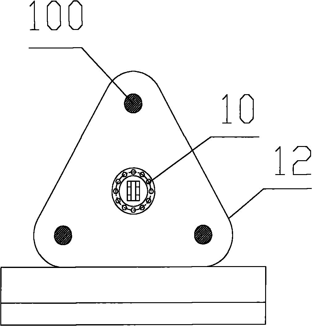
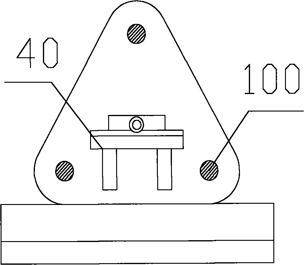
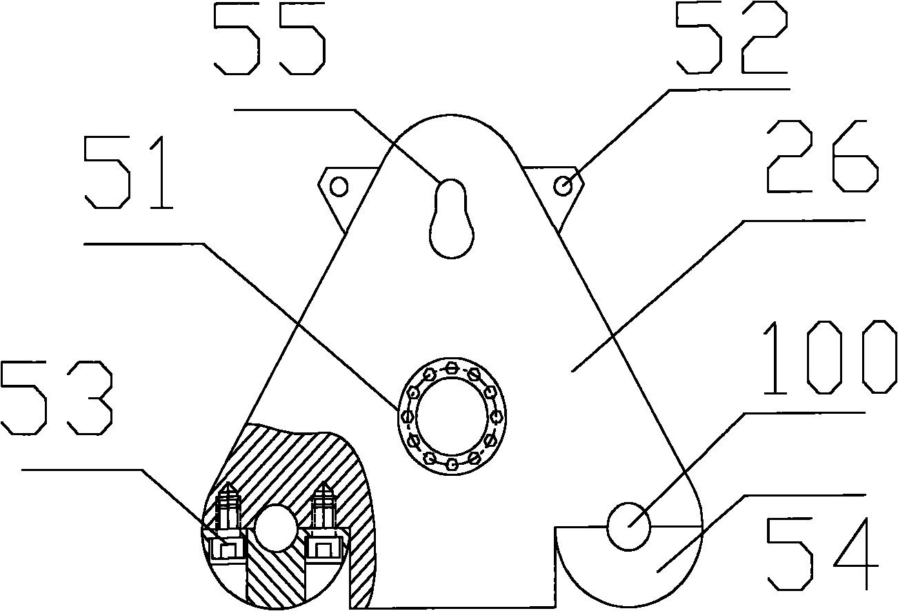
[0032] The reference numerals and components involved in the drawings are as follows:

[0033] 10 Trunnion support 12 Fixed triangle plate

[0034] 20 cylinder under test 21V iron

[0035] 22 jack 24 fixed rail

[0036] 26 Movable triangle plate 27 Trunnion connector of the tested cylinder and the loading cylinder

[0037] 30 Base 32 Take over for connecting cylinder

[0038] 35 Loading cylinder for trunnion cylinder test 36 Pedestal mounting cylinder for loading test cylinder

[0039] 40 Support base 51 Base plate for fixing oil cylinder or trunnion

[0040] 52 Lifting holes for lifting movable triangle plate 53 Bolts

[0041] 54 Semicircular ring for fixed movable triangular plate 55 Taper hole

[0042] 100 rail holes

[0043] Please see figure 1 , figure 2 with image 3 . figure 1 It is a schematic diagram of the structure of the fixed triangle plate in the tripod for cylinder test. figure 2 It is a schematic diagram of the structure of the support base in the tripod for the cylinder tes...

Embodiment 2

[0051] Example 2 Conventional hydraulic cylinder test method (take trunnion hydraulic cylinder experiment as an example)

[0052] Test method for external leakage of hydraulic cylinder

[0053] press Figure 4 Install the tested hydraulic cylinder, loading hydraulic cylinder, hydraulic pipeline, etc. in place, connect the tested hydraulic cylinder to the loading cylinder with a trunnion connector, and adjust the centering with an adjustment guide frame.

[0054] Please see Figure 10A , Turn on the hydraulic system of the tested hydraulic cylinder, switch the reversing valve 230 to the left position, adjust the one-way throttle valve 211; switch the reversing valve 230 to the right position, adjust the one-way throttle valve 212; make the piston reciprocate several times, Side by side despite the air in the channel, when the tested hydraulic cylinder 222 is in place, adjust the overflow valve 209 to be used as a safety valve. Adjust the overflow valves 206 and 205 to gradually increa...

Embodiment 3

[0059] Example 3 Test method of hydraulic cylinder subjected to impact load (taking the experiment of trunnion hydraulic cylinder as an example)

[0060] Please see Figure 10B , Install the tested hydraulic cylinder 222, the impact slide valve 223, etc., turn on the tested hydraulic cylinder 222, load the hydraulic cylinder to test the hydraulic system, switch the reversing valve 230 to the left position, and adjust the overflow valve 309 to gradually increase the load pressure to 120% , The loading cylinder simulates the load to push the tested hydraulic cylinder, when the tested hydraulic cylinder piston moves to the position to be tested, close the high-pressure ball valves 210, 220, 270, 280; close the high-pressure ball valves 360, 370, 380, 390, and open the high-pressure ball valves 310, 3201, 340, 350 At this time, the hydraulic system of the loading hydraulic cylinder adopts the impact hydraulic circuit composed of the quick reversing valve 302 and the impact slide valve...


PUM


Abstract

The invention relates to a hydraulic cylinder test device and method under a simulated working condition, wherein the hydraulic cylinder test device is provided with a loading oil cylinder hydraulic device, a tested oil cylinder hydraulic device and a triangle frame for the test of the oil cylinder which are connected by hydraulic pipelines. The invention also provides a hydraulic oil cylinder test method under the simulated working condition. The dependence of the hydraulic cylinder test device under the simulated working condition on the technique and experiences of inspectors is reduced, the loading test is carried out at the whole process at any position, and the test pressure can be selected according the actual working condition of the tested oil cylinder; and when in test, if the quality can not be well controlled, after the repaired hydraulic oil cylinder is used on line for a period of time, the external leakage of the hydraulic cylinder can cause serious pollution to the field environment, and simultaneously the great waste of the lubricating oil can be caused, thus the service life is influenced, and once an accident occurs, inestimable loss can be caused.

Description

【Technical Field】 [0001] The invention relates to a hydraulic cylinder test device, in particular to a hydraulic cylinder test device and a test method that simulate working conditions. 【Background technique】 [0002] Hydraulic cylinder testing includes no-load test, internal leakage test, external leakage test, etc. Corresponding tests must be carried out after the hydraulic cylinder is repaired. Cylinders are generally not used at both ends of the full stroke. The cylinders with more abrasion are generally in the common working positions of cylinders, and some cylinders have to withstand impact loads. Existing hydraulic cylinder tests cannot meet this requirement. When the installation position of the oil cylinder is different from the load running track, the piston rod and the seal are often worn out on one side. In the current test project, there is no targeted loading device according to the on-site installation and usage. The test is usually It is difficult to meet Party A...

Claims


Application Information

Patent Timeline
Patent Type & Authority Applications(China)
IPC IPC(8): F15B19/00
Inventor 徐天亮
Owner NANJING MEISHAN METALLURGY DEV
Learn More