Spatial flexible coupling

A flexible coupling, space technology, used in elastic couplings, couplings, mechanical equipment, etc., can solve problems such as inability to transmit torque

Inactive Publication Date: 2011-11-23
吴实渊
View PDF0 Cites 8 Cited by
  • Summary
  • Abstract
  • Description
  • Claims
  • Application Information

AI Technical Summary

Problems solved by technology

They found that if the coupling mass is too heavy, torque cannot be transmitted

Method used


Image

  • Spatial flexible coupling
  • Spatial flexible coupling

Examples


Embodiment Construction

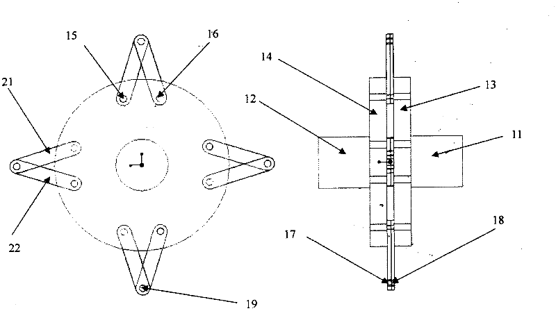
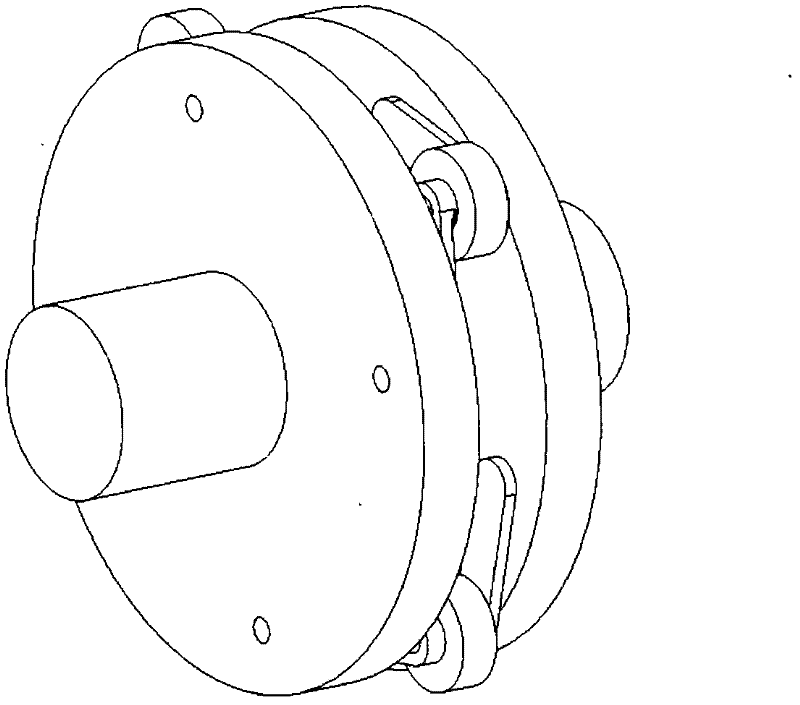
[0014] For plotting especially the initial figure 1 , is the connection of the drive shaft 11 to the driven shaft 12 of the spatially flexible coupling. The coupling includes an input flange 13 mounted on the driving shaft 11 and an output flange 14 mounted on the driven shaft 12 . There are three holes of the same diameter evenly distributed on the periphery of the flange. Flanges 13 and 14 are fastened to shafts 11 and 12; the two flanges 13 and 14 have the same geometrical dimensions, but may differ in thickness. Located between the two flanges 13 and 14 are three identical coupling masses 19 , positioned generally parallel to the axes 11 and 12 . Twelve identical spherical bearings are mounted on the flange and coupling mass, three spherical bearings 15 on the input flange, three spherical bearings 16 on the output flange, three spherical bearings 17 on the side facing the input flange On the coupling mass, three spherical bearings 18 are on the coupling mass facing the...


PUM

PropertyMeasurementUnit
Axis angleaaaaaaaaaa

Abstract

The invention discloses a spatial flexible coupling, namely a spatial dynamic linked coupling. The spatial flexible coupling is used for transmitting rotating mechanical power, providing extremely low torsional rigidity so as to achieve isolation of torsional vibration and allowing an angle between a driven shaft and a driving shaft. In the system, an input flange fixed on the driving shaft is connected to coupling masses of the same number through pivots at the outer ends of a plurality of link arms with equal length; and pivots at the inner ends of the link arms are connected to the input flange through holes uniformly distributed in the circumference of the flange. The coupling masses are sequentially connected to an output flange fixed on the driven shaft through the pivots of the link arms of the same number. Spherical bearings are arranged in the connecting holes in the flanges and the coupling masses. The axes of two shafts can be placed in an acute angle, and the two shafts are not limited on the same axis. During moving, the driving shaft guides the driven shaft, so that the torque is used as tension and transmitted in the link arms. Because of the action of the spherical bearings, the link arms can adapt to the angle change of the shafts during rotating.

Description

technical field [0001] This invention relates to spatially flexible couplings for the transmission of power between a drive shaft and a driven shaft or other rotating tool. Spatially flexible couplings can transmit low to high power at high speeds and offer extremely low torsional stiffness. More particularly, the present invention allows an angle between the drive shaft and the driven shaft when transmitting power. technical background [0002] Georgevitch's invention (US# 1,716,225, 1929) is limited in the ability to transmit torque, and the range of angles allowed between shafts. Since the transmitted torque is balanced with the centrifugal force acting on the link arm, under the condition of low speed and high torque, the two link arms will be easily coaxial, which will lead to the instability of the system motion. On the other hand, the link arm used in this invention is a non-rubber-plastic material, which hardly allows a small misalignment, and the two ends of the l...

Claims


Application Information

Patent Timeline
IPC IPC(8): F16D3/60
Inventor 吴实渊查尔斯·伯特
Owner 吴实渊
Why Eureka
Try Eureka