Clearance compensation mechanism of gas-pressure plate type brake

A disc brake and clearance compensation technology, applied in the direction of slack adjusters, etc., can solve the problems of increased manufacturing cost, complex structure, and difficult assembly by workers, and achieve the effects of guaranteed service life, simple mechanism, and easy assembly

Active Publication Date: 2013-09-04
ZHEJIANG VIE SCI & TECH
View PDF1 Cites 0 Cited by
  • Summary
  • Abstract
  • Description
  • Claims
  • Application Information

AI Technical Summary

Problems solved by technology

[0006] The National Patent Office of China published the patent No. "200620099779.8" on 2008-2-27, and the patent named "Floating Clamp Double Push Rod Pneumatic Disc Brake", which improves the braking torque of the brake and makes it more stable; improves The movement synchronization of the double push rods is improved, so that the overall performance of the air disc brake is further improved; however, the clearance adjustment mechanism used in this patent mainly uses the principle of combining double torsion springs and adjustment sleeves, and its disadvantages are: 1. The torsion spring is installed between the adjustment sleeve and the rotating ring. The structure is complex and difficult for workers to assemble. Second, the transmission process during gap compensation requires the cooperation of large and small torsion springs. The accuracy of gap adjustment depends on the two torsion springs. Otherwise, the service life of the brake cannot be guaranteed; 3. The double torsion spring structure makes the structure of the gap adjustment mechanism complex and the manufacturing cost increases

Method used


Image

  • Clearance compensation mechanism of gas-pressure plate type brake
  • Clearance compensation mechanism of gas-pressure plate type brake
  • Clearance compensation mechanism of gas-pressure plate type brake

Examples


Embodiment Construction

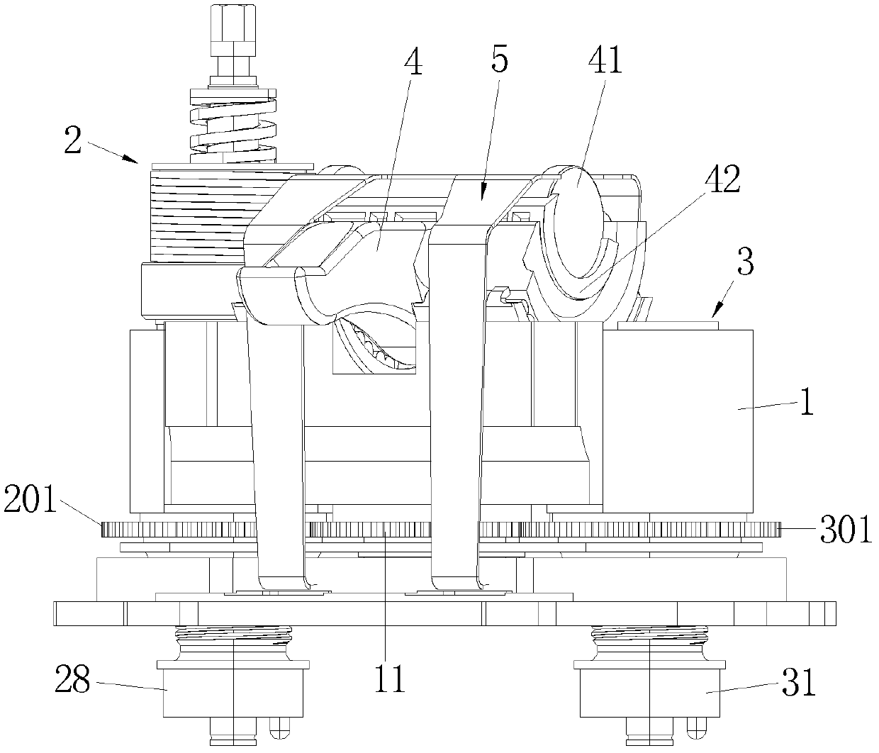
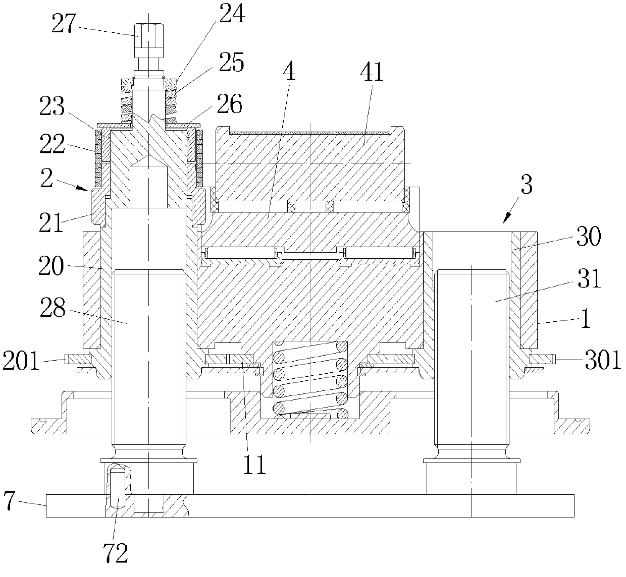
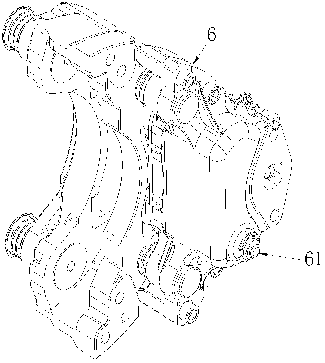
[0026] refer to Figure 1-4 , a gap compensation mechanism for an air pressure disc brake, comprising a booster mechanism, a support base 1, an active adjustment mechanism 2 and a driven adjustment mechanism 3 arranged at both ends of the support base 1, and connecting the active adjustment mechanism 2 and the driven adjustment mechanism 3 The transmission structure, the push plate 7 jointly driven by the active adjustment mechanism 2 and the driven adjustment mechanism 3; the active adjustment mechanism 2 includes a drive shaft assembly rotatably connected to one end of the support base 1 and an adjustment sleeve movably sleeved on the drive shaft assembly 21. The booster mechanism drives the active adjustment mechanism 2 to act while driving the support base 1 forward. Through the transmission of the transmission structure, the driven adjustment mechanism 3 and the active adjustment mechanism 2 operate synchronously to push the push plate 7 to complete the gap compensation. T...


PUM


Abstract

The invention discloses a clearance compensation mechanism of a gas-pressure plate type brake, comprising a force increasing mechanism, a support base, a driving adjustment mechanism, a driven adjustment mechanism, a transmission mechanism, a pushing plate and a ferrule, wherein the driving adjustment mechanism and the driven adjustment mechanism are arranged at two ends of the support base, the transmission mechanism is connected to the driving adjustment mechanism and the driven adjustment mechanism, and the pushing plate is jointly driven by the driving adjustment mechanism and the driven adjustment mechanism; the driving adjustment mechanism comprises a driving shaft assembly rotatably connected to one end of the support base and an adjusting sleeve movably sleeved on the driving shaft assembly; the force increasing mechanism drives the driving adjustment mechanism to work while driving the support base to advance, the driven adjustment mechanism and the driving adjustment mechanism synchronously work to push the pushing plate to finish clearance compensation via the transmission of the transmission mechanism; the ferrule is arranged on the driving shaft assembly via a locating mechanism; and the ferrule and the adjusting sleeve are tightly held and ganged via a torsion spring. A one-way clutch structure formed by the torsion spring, the adjusting sleeve and the ring is simply structured and easily assembled and is low in cost.

Description

technical field [0001] The present invention relates to an air disc brake, and more particularly to a gap compensation mechanism in an air disc brake. Background technique [0002] Automobile brakes are mainly divided into two types: drum type and disc type. Drum type brakes are low in cost, dustproof, and convenient to be used as parking brakes at the same time, but their braking efficiency and heat dissipation are much worse, and the stability of braking force of drum type brakes is poor. The braking force varies greatly on different road surfaces, which is not easy to control, and due to poor heat dissipation, a large amount of heat will be accumulated during braking; brake pads and wheel drums are prone to extremely complex deformations under the influence of high temperatures, and are easy to Braking fading and chattering will occur, resulting in a decrease in braking efficiency. [0003] The disc brake has a large and stable braking force under the hydraulic power ass...

Claims


Application Information

Patent Timeline
Patent Type & Authority Patents(China)
IPC IPC(8): F16D65/52
Inventor 王涛傅炎木
Owner ZHEJIANG VIE SCI & TECH
Why Eureka
Try Eureka