Vehicle headlamp

A technology for headlights and vehicles, applied in lighting devices, fixed lighting devices, lighting and heating equipment, etc., can solve the problems of light utilization rate reduction and achieve the effect of improving light utilization rate

Active Publication Date: 2011-11-23
STANLEY ELECTRIC CO LTD
View PDF4 Cites 8 Cited by
  • Summary
  • Abstract
  • Description
  • Claims
  • Application Information

AI Technical Summary

Problems solved by technology

[0011] Third, when any light distribution pattern is formed, the baffle plate 150 blocks part of the light, resulting in a reduction in the utilization rate of light.

Method used


Image

  • Vehicle headlamp
  • Vehicle headlamp
  • Vehicle headlamp

Examples


Embodiment Construction

[0032] Hereinafter, embodiments of the present invention will be described with reference to the drawings.

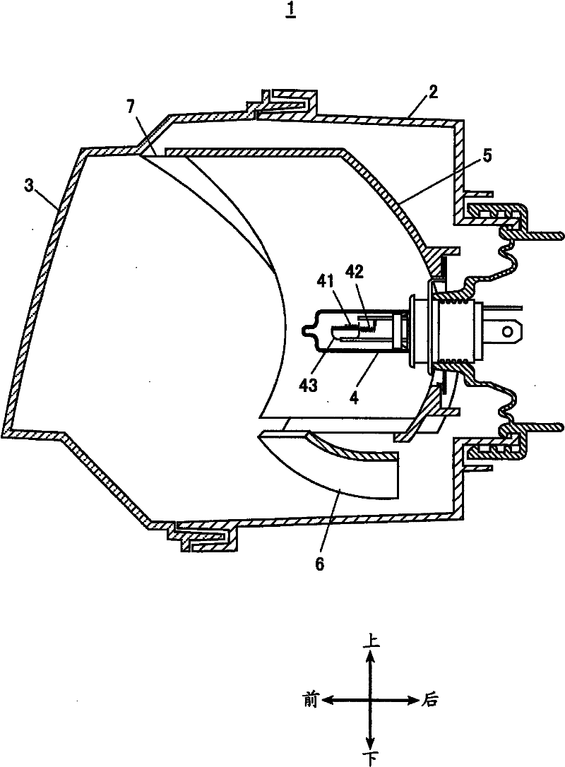
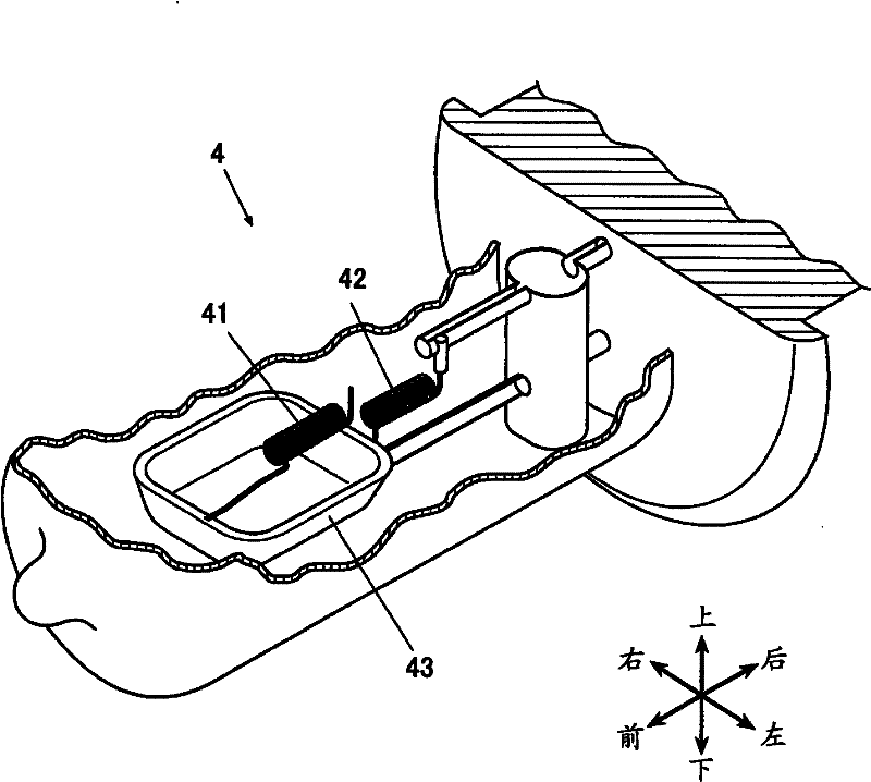
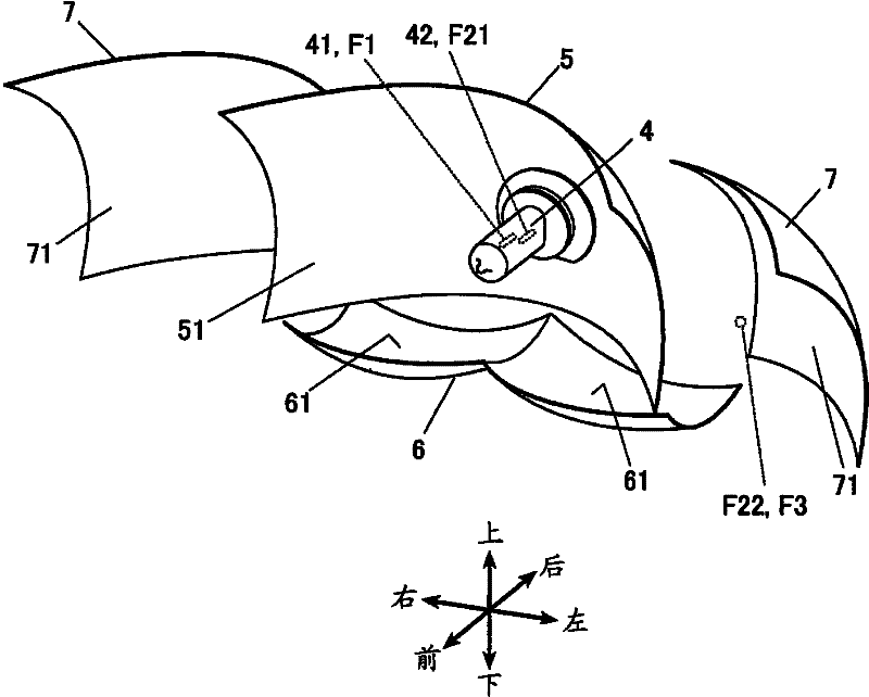
[0033] figure 1 It is a side sectional view of the vehicle headlamp 1 in this embodiment, figure 2 is a perspective view of a bulb 4 included in a vehicle headlamp, image 3 and Figure 4 It is a perspective view and a front view showing important parts of the vehicle headlamp 1 .

[0034] In addition, in the following description, expressions of "front", "rear", "left", and "right" refer to directions of a vehicle equipped with the vehicle headlamp 1 . Similar expressions such as "front" and "front" are also the same.

[0035] Such as figure 1 As shown, the vehicular headlamp 1 has: a lamp body 2 which is opened at the front; and a light-transmitting cover 3 arranged to cover the front opening of the lamp body 2 . A light bulb 4 , a first reflector 5 , a second reflector 6 and two third reflectors 7 , 7 are accommodated in the lamp chamber formed by the lamp b...


PUM


Abstract

The invention discloses a vehicle headlamp, which can switch light distribution patterns without movable portions so as to form light distribution patterns respectively adapted to far-light beams and dipped beams. Meanwhile, glare is not generated when the dipped beams are formed, so that the utilization rate of light is improved compared with the prior art. The vehicle headlamp (1) comprises a bulb (4) equipped with a first filament (41) and a second filament (42), a first reflecting surface (51) of a parabolic line with a focus (F1) near the first filament (41), a second reflecting surface (61) of an elliptic system with a first focus (F21) near the second filament (42) so as to enable the ejaculation light of the second filament (42) to reflect toward a second focus (F22) and a third reflecting surface (71) of a parabolic line with a focus (F3) near the second focus (F2) of the second reflecting surface (61). The bulb (4) is equipped with a light shield (43) close to the first filament (41). The light shield (43) is used for shielding the light from the first filament (41) to the second reflecting surface (61).

Description

technical field [0001] The present invention relates to a vehicle headlamp. Background technique [0002] As a binocular type vehicle headlamp such as a motorcycle headlamp, a scheme capable of switching a light distribution pattern between a high beam and a low beam without providing a movable part has been proposed (for example, refer to Patent Document 1). [0003] Such as Figure 7 As shown, the vehicle headlamp 100 has: a bulb 110, which has a first light emitting portion 111 and a second light emitting portion 112 arranged up and down; It has a focal point below and near the first light-emitting part 111; the second reflective surface 130, 130 of the ellipse system, which is arranged above the bulb 110, has a first focus near the second light-emitting part 112, and its major axis is on the left and right extending in the direction; the third reflective surface 140,140, ​​which takes the second focal point of the second reflective surface 130,130 as the focal point an...

Claims


Application Information

Patent Timeline
Patent Type & Authority Applications(China)
IPC IPC(8): F21S8/10F21V13/10F21W101/10
Inventor 大野克司
Owner STANLEY ELECTRIC CO LTD
Why Eureka
Try Eureka