Close object imaging apparatus

An imaging device and short-distance technology, applied in the field of optical imaging, can solve the problems of limiting the application of short-distance imaging devices, low reliability of short-distance imaging devices, and heavy weight of short-distance imaging devices, and achieve easy movement and placement, and easy Manufacturing and assembly, good imaging results

Active Publication Date: 2011-11-23
陈晖
View PDF3 Cites 4 Cited by
  • Summary
  • Abstract
  • Description
  • Claims
  • Application Information

AI Technical Summary

Problems solved by technology

[0004] However, the short-distance imaging device must be designed to ensure that the facet angle on the right end surface of the wedge-shaped plate is consistent with the ideal design value, and a slight deviation will cause the converging point of the light on the left end surface to differ from the ideal converging point in design. A certain distance deviation will affect the definition of imaging; in the actual design and production process, a large number of tiny facets can be engraved on the small area of ​​the right end of the wedge-shaped plate. Distance imaging devices are less reliable and more expensive to manufacture
At the same time, the wedge-shaped flat plate is usually made of plexiglass, and its volume density is relatively high, so that the weight of the short-distance imaging device is relatively large, which limits the application of the short-distance imaging device in many occasions.

Method used


Image

  • Close object imaging apparatus
  • Close object imaging apparatus
  • Close object imaging apparatus

Examples


Embodiment Construction

[0027] In order to describe the present invention more specifically, the technical solutions of the present invention and related imaging principles will be described in detail below in conjunction with the accompanying drawings and specific embodiments.

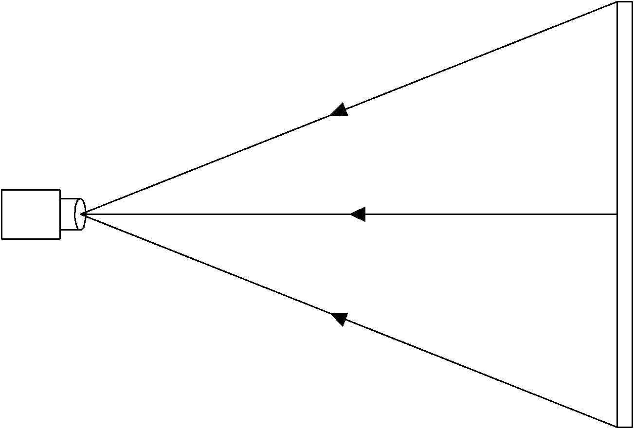
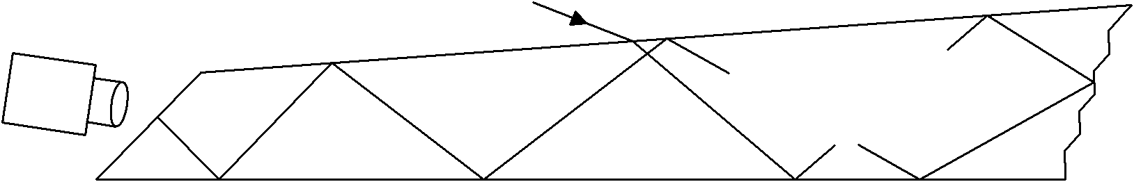
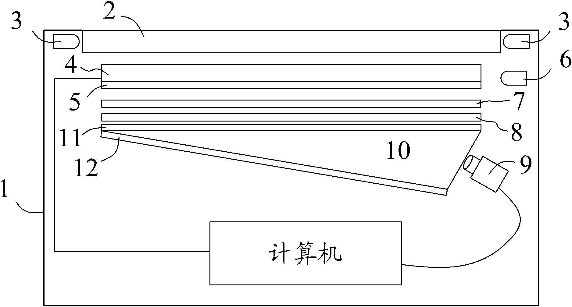
[0028] Take the application of the imaging device of the present invention in a flat touch computer as an example, such as image 3 As shown, the flat touch computer includes a housing 1, the top of the housing 1 is provided with a transparent flat panel 2; the transparent flat panel 2 is plexiglass, its upper surface has a layer of scattering medium, and its two sides are respectively provided with two infrared light emitting diodes 3 (InfraredLED); the infrared light emitted by the infrared light-emitting diode 3 enters the transparent flat plate 2 and is continuously totally reflected between the upper and lower surfaces; since the upper surface of the transparent flat plate 2 has a layer of scattering medium, the infrared...


PUM


Abstract

The invention discloses a close object imaging apparatus which comprises a light filter layer used for filtering light whose incidence angle is greater than a filtering angle in object scattered light, a Fresnel Lenses used for focusing light whose focusing incidence angle is less than the filtering angle, a wedge form light guide used for folding focused light, and an image sensor used for receiving folded focused light at a focus point. According to the imaging apparatus in the invention, through reasonable and ingenious structural design, object close imaging is realized without fine technical manufacture, and the imaging apparatus has high imaging sharpness and is easy to manufacture and assembling. Simultaneously, light and thin optical type elements are employed, and the whole apparatus has small volume and light weight and is easy to move and place. The imaging apparatus can be widely used for close object imaging in various fields.

Description

technical field [0001] The invention belongs to the technical field of optical imaging, and in particular relates to a short-distance object imaging device. Background technique [0002] Traditional object imaging devices and methods are very simple, such as figure 1 As shown, the image sensor is set at a certain distance from the planar object, and the light emitted by the planar object is focused on the image sensor, thereby forming an image of the planar object through the image sensor. However, in order to obtain an image with uniform brightness and true proportions, according to the optical principle, the traditional imaging device for planar objects must place the image sensor far away from the planar object. Cause the whole device to be too bulky. [0003] The U.S. Patent No. US 7,660,047B1 discloses a short-range imaging device, such as figure 2 As shown, it places the left end surface of a transparent wedge-shaped flat plate in front of the lens of the image sen...

Claims


Application Information

Patent Timeline
Patent Type & Authority Applications(China)
IPC IPC(8): G02B6/00
CPCG06F3/0421G02B3/08G02B6/0046G06F3/00G02B6/00
Inventor 陈晖
Owner 陈晖
Why Eureka
Try Eureka