Connector and printed circuit board foot pattern for a connector

A technology for printed circuit boards and connectors, applied in the directions of printed circuit components, electrical connection printed components, circuits, etc., can solve the problems of weak differential bonding force and inability to transmit efficiently, to suppress crosstalk and avoid impedance. mismatched effects

Active Publication Date: 2014-12-24
HOSIDEN CORP
View PDF4 Cites 0 Cited by
  • Summary
  • Abstract
  • Description
  • Claims
  • Application Information

AI Technical Summary

Problems solved by technology

[0006] However, in the above-mentioned Patent Document 1, since the terminal parts are arranged at equal intervals, although it is advantageous to reduce the cost of the connector, reduce the size and narrow the pitch, but on the side of the printed circuit board or the cable that becomes the connection object of the connector, use The differential wiring that is firmly differentially bonded between the paired differential lines also has to be arranged at a pitch equal to the pitch between the terminal parts from the front of the connector.
Therefore, there is a problem that, at the connection portion between the connector and the connection object, the differential coupling force between the differential lines becomes weak, and efficient transmission cannot be performed.

Method used


Image

  • Connector and printed circuit board foot pattern for a connector
  • Connector and printed circuit board foot pattern for a connector
  • Connector and printed circuit board foot pattern for a connector

Examples


Embodiment Construction

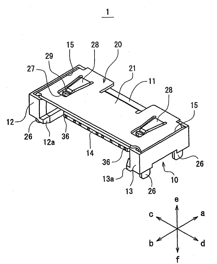
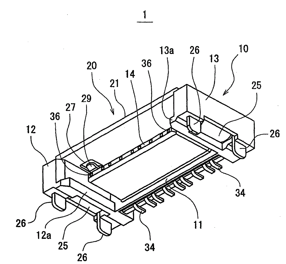
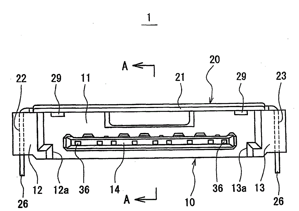
[0026] Below, refer to Figure 1 ~ Figure 9C A connector according to one embodiment of the present invention will be described. Additionally, in the description below, the figure 1 The direction of the arrow line a-b is taken as the front-rear direction (length direction) of the connector, the direction of the arrow line c-d is taken as the left-right direction (width direction) of the connector, and the direction of the arrow line e-f is taken as the up-down direction (height direction) of the connector.

[0027] The connector 1 of this embodiment is a receptacle in which an unillustrated plug provided at the end of a connecting cable between electronic devices serves as a mating-side connector, and the connector 1 is mounted on a printed circuit board ( PCB) 100 (refer to Figure 7 ), can be separately mated and connected with the mating side connector, and transmit high-speed differential signals between electronic devices. Furthermore, the connector 1 of the present em...


PUM


Abstract

A connector, and printed circuit board foot pattern for a connector which can efficiently transmit a high-speed differential signal are provided. In a connector 1, a contact group 30 includes at least paired adjacent signal contacts SC-SC, and non-paired contacts GC which are placed on both adjacent sides or one adjacent side of the paired signal contacts. The contacts are arranged so that the distance W1 between the paired signal contacts SC-SC is shorter than the distance W2 between adjacent signal and non-paired contacts SC-GC, thereby enhancing the differential coupling force between the paired signal contacts SC-SC.

Description

technical field [0001] The present invention relates to a connector for transmitting high-speed differential signals and a printed circuit board foot pattern for connector. Background technique [0002] Conventionally, a connector has a contact group and an insulator holding the contact group. Each contact of the contact group has a terminal part connected to a connection object and a contact part connected to a mating side contact. Each contact Arranged at equal intervals along the pitch direction perpendicular to the mating and separating direction from the terminal part to the contact part in parallel in the mating and separating direction of the connector and the mating side connector and the distance between adjacent contacts is all equal, The arrangement of the contacts at equal intervals contributes to the cost reduction, productivity improvement, miniaturization and narrow pitch of the connector. [0003] However, in differential transmission, if the distance betwee...

Claims


Application Information

Patent Timeline
Patent Type & Authority Patents(China)
IPC IPC(8): H01R13/6471H01R12/55H05K1/11
CPCH05K1/0253H01R12/725H01R13/6471H01R12/70H01R12/71
Inventor 近藤快人三吉利治
Owner HOSIDEN CORP
Why Eureka
Try Eureka