Method and device for reducing inter-cell interference

A technology of inter-cell interference and cell, applied in electrical components, wireless communication, etc., can solve the problems of reducing UE transmission power, reducing the overall performance of the LTE system, resource waste, etc., and achieve the effect of avoiding repeated interference

Inactive Publication Date: 2011-11-23
POTEVIO INFORMATION TECH
View PDF3 Cites 20 Cited by
  • Summary
  • Abstract
  • Description
  • Claims
  • Application Information

AI Technical Summary

Problems solved by technology

[0004] Reducing the transmit power of the UE wastes resources on the one hand and reduces the overall performance of the LTE system. On

Method used


Image

  • Method and device for reducing inter-cell interference
  • Method and device for reducing inter-cell interference
  • Method and device for reducing inter-cell interference

Examples


Embodiment 1

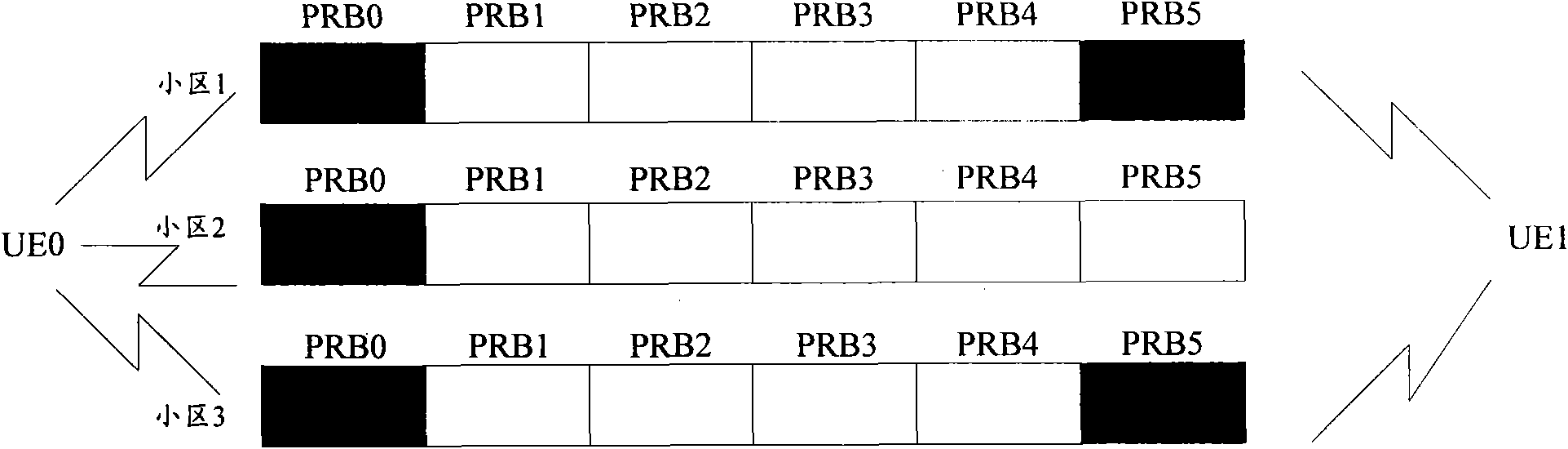
[0036] In this embodiment, the serving cells of UE0 and UE1 are cell 3, and cell 0, cell 1 and cell 2 are adjacent cells of cell 3. figure 2 It is a schematic diagram of cell interference in this embodiment.

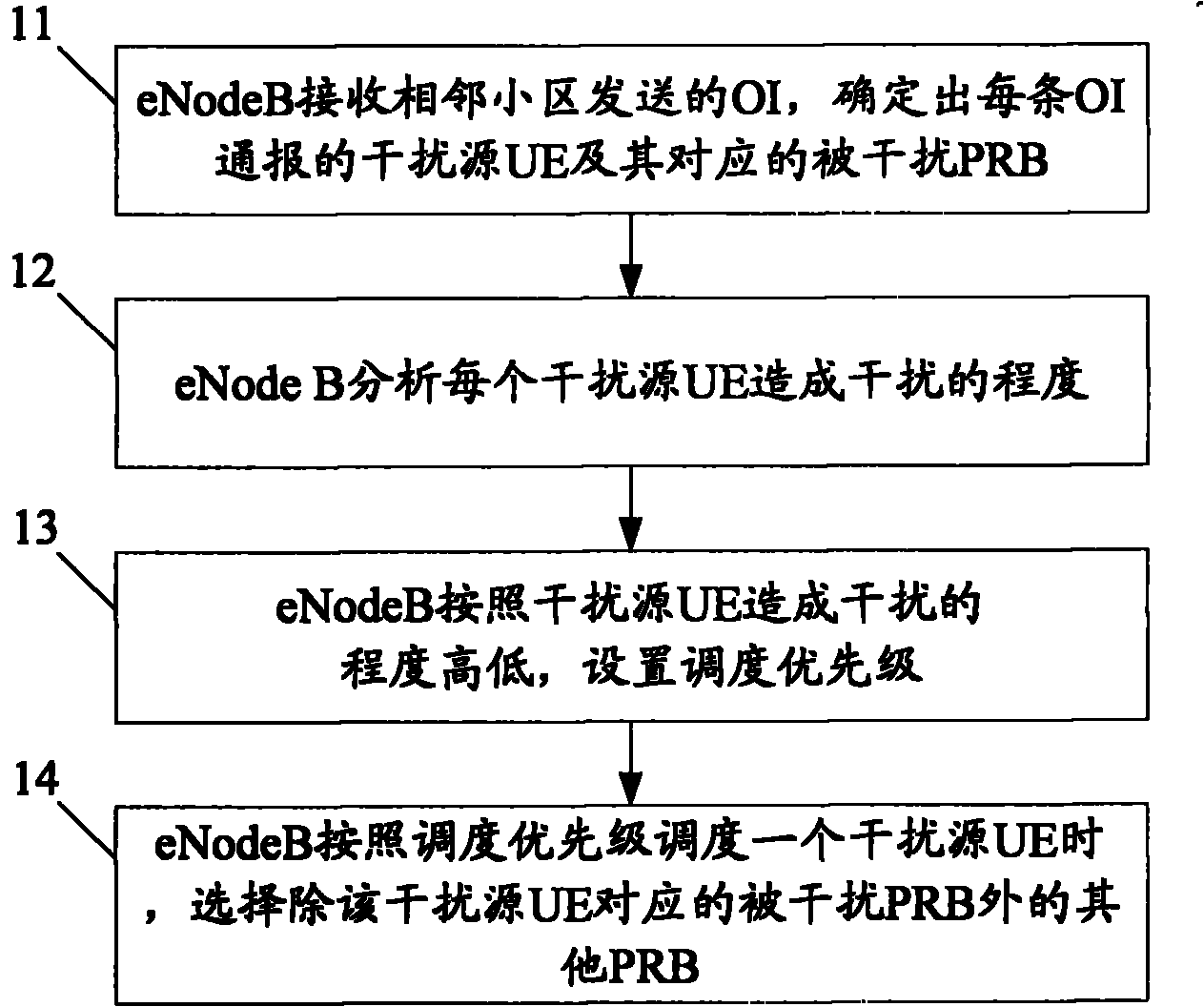
[0037] The process in this embodiment includes the following steps:

[0038] Step 21: The eNode B of cell 3 receives the OIs sent by cell 0, cell 1, and cell 2 respectively. The OI sent by cell 0 notifies that UE0 interferes with PRB0 of cell 0, and that UE1 interferes with PRB5 of cell 0. Cell 1 The sent OI notifies that UE0 interferes with PRB0 of cell 1, and the OI sent by cell 2 notifies that UE0 interferes with PRB0 of cell 2, and that UE1 interferes with PRB5 of cell 2.

[0039] Step 22: The eNode B of cell 3 respectively determines the number of cells that are interfered by UE0 and UE1.

[0040] In this step, the eNode B of cell 3 determines that the number of OIs notified to UE0 is 3, thereby determining that the number of cells causing interference by UE0 is ...

Embodiment 2

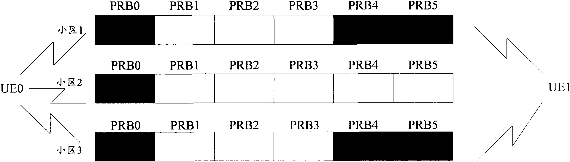
[0044] In this embodiment, the serving cells of UE0 and UE1 are cell 3, and cell 0, cell 1 and cell 2 are adjacent cells of cell 3. image 3 It is a schematic diagram of cell interference in this embodiment.

[0045] The process in this embodiment includes the following steps:

[0046] Step 31: The eNode B of cell 3 receives the OI sent by cell 0, cell 1 and cell 2, wherein the OI sent by cell 0 notifies that UE0 interferes with PRB0 of cell 0, and that UE1 interferes with PRB4 and PRB5 of cell 0. The OI sent by 1 notifies that UE0 interferes with PRB0 of cell 1, the OI sent by cell 2 notifies that UE0 interferes with PRB0 of cell 2, and that UE1 interferes with PRB4 and PRB5 of cell 2.

[0047] Step 32: The eNode B of cell 3 determines that the number of interfered PRBs corresponding to UE0 is 3, and the number of interfered PRBs corresponding to UE1 is 4.

[0048] Step 33: The eNode B of cell 3 determines that the scheduling priority of UE1 is higher than that of UE0.

[00...


PUM


Abstract

The invention discloses a method and device for reducing inter-cell interference. The method comprises the following steps of: receiving overload indications sent by an adjacent cell through a base station, and determining interference source user equipment notified by each overload indication and an interfered physical resource block corresponding to the interference source user equipment; analyzing the degree of interference caused by each interference source user equipment; setting a dispatching priority according to the degree of interference caused by the interference source user equipment; and when the base station dispatches one interference source user equipment according to the dispatching priority, selecting other physical resources blocks except for the interfered physical resource block corresponding to the interference source user equipment. By using the method provided by the invention, the interference source user equipment causing interference can be dispatched in time, and the repeated occurrence of interference can be avoided.

Description

technical field [0001] The present invention relates to the field of long term evolution (Long Term Evolution, LTE) of Universal Mobile Telecommunications System (Universal Mobile Telecommunication System, UMTS), in particular to a method and device for reducing inter-cell interference in the LTE system. Background technique [0002] In order to improve resource utilization, the resource scheduling technology is adopted in the LTE system, so that multiple user equipments (User Equipment, UE) in multiple cells can share wireless resources. (PRB). [0003] Interference between cells is an inherent problem in cellular mobile communication systems, and LTE systems are no exception. Currently, the LTE system adopts a scheme based on High Interference Indication (High Interference Indication, HII) and Overload Indication (OI). The base station (eNode B, E-UTRAN NodeB) uses HII to notify adjacent cells of PRBs that may be interfered, and uses OI to notify adjacent cells of the in...

Claims


Application Information

Patent Timeline
IPC IPC(8): H04W72/08H04W72/12
Inventor 洪伟
Owner POTEVIO INFORMATION TECH
Why Eureka
Try Eureka