Brake cylinder device and unit brake

A brake cylinder, commonly used brake technology, applied in the direction of brakes, brake types, brake components, etc., can solve problems such as increased reaction force

Active Publication Date: 2011-11-23
NABLESCO CORP
View PDF6 Cites 20 Cited by
  • Summary
  • Abstract
  • Description
  • Claims
  • Application Information

AI Technical Summary

Problems solved by technology

In particular, when the biasing force of the first piston is high during parking, the reaction force from the brake shoe side becomes larger, and this tendency becomes more prominent.

Method used


Image

  • Brake cylinder device and unit brake
  • Brake cylinder device and unit brake
  • Brake cylinder device and unit brake

Examples


no. 1 Embodiment approach

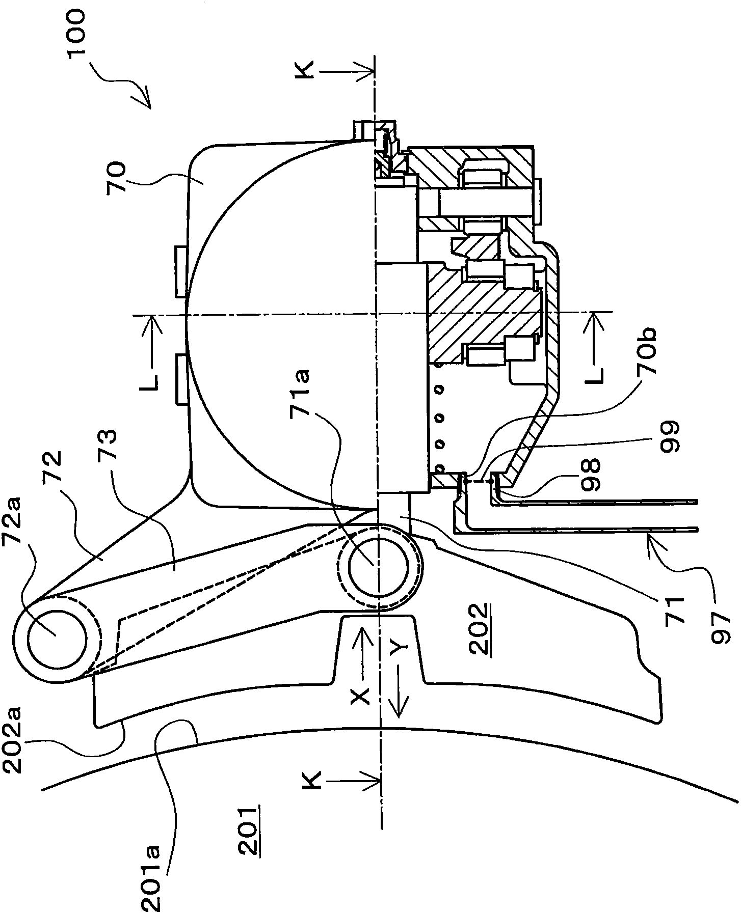
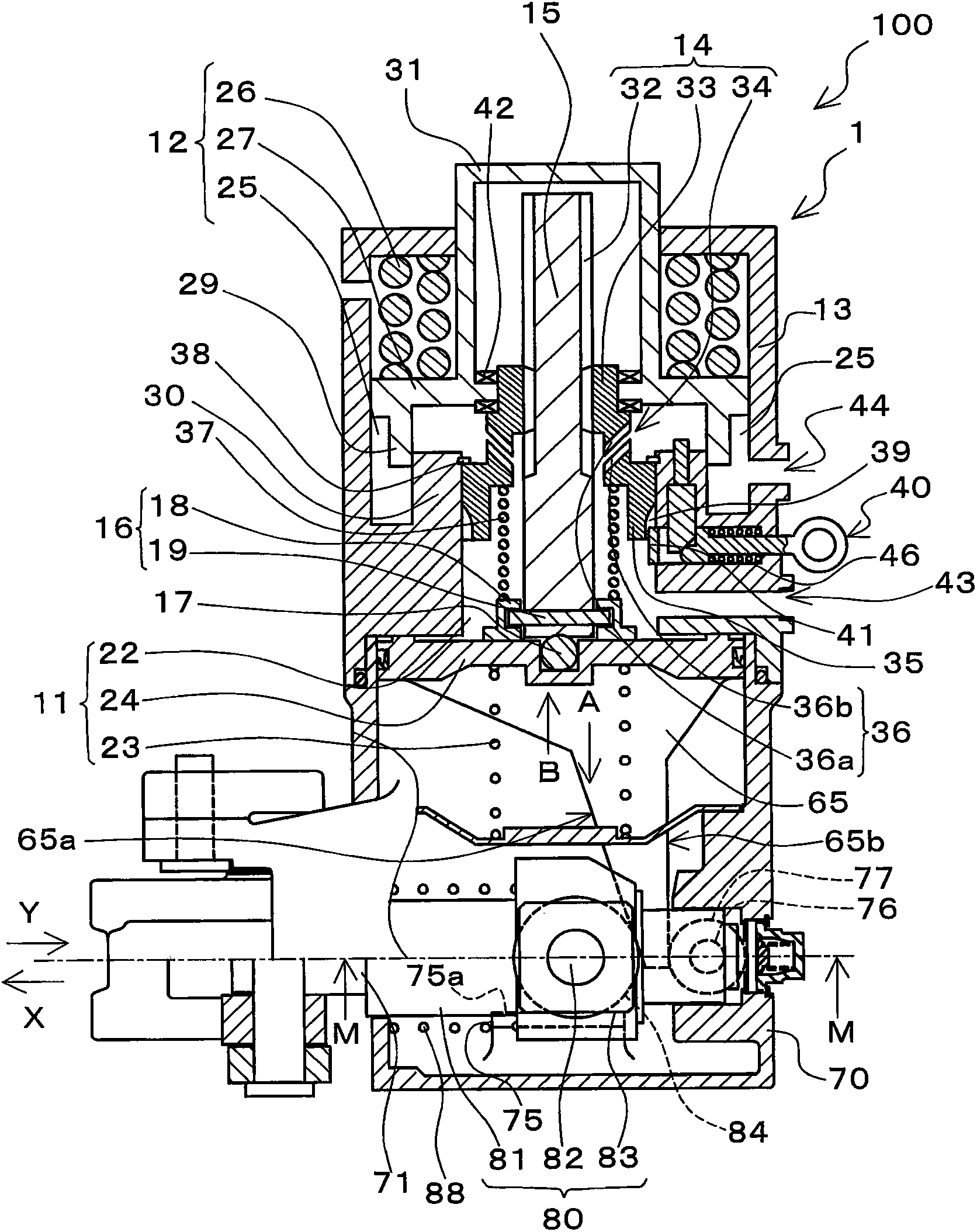
[0061] A brake cylinder device and a unit brake according to a first embodiment of the present invention will be described. figure 1 It is a partial cross-sectional view viewed from the axial direction of a wheel 201 when the unit brake 100 of the first embodiment is mounted on a vehicle. figure 2 is along figure 1 A partial cross-sectional view at the position observed in the direction of the K-K line.

[0062] figure 1 and figure 2 The illustrated unit brake 100 includes the brake cylinder device 1 of the first embodiment and a box-shaped brake body 70 for mounting the brake cylinder device 1 and covering a part of a drive mechanism of the brake. Furthermore, the unit brake 100 is configured to brake the brake shoe 202 held relatively movable with respect to the brake main body 70 by actuating at least one of the service brake mechanism 11 and the spring brake mechanism 12 described later. The surface 202a abuts against the tread surface 201a of the wheel 201 of the ve...

no. 2 Embodiment approach

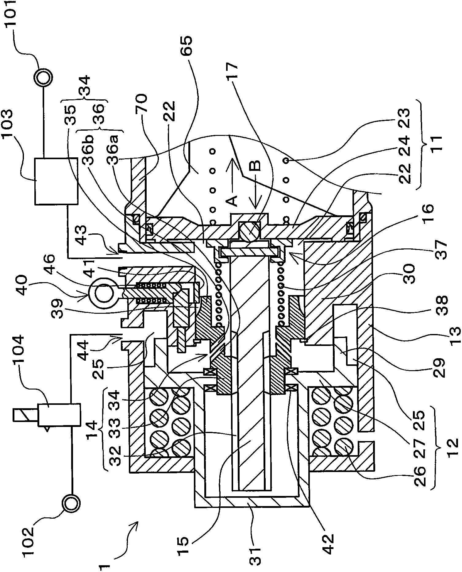
[0116] A unit brake 110 according to a second embodiment of the present invention will be described. Figure 12 It is a partial sectional view of the unit brake 110 of the second embodiment. Figure 12 The illustrated unit brake 110 includes: the brake cylinder device 2 according to the second embodiment; and a brake main body 70 formed in a box shape to cover a part of a drive mechanism of the brake to which the brake cylinder device 2 is attached. The unit brake 110 with figure 1 The unit brake 100 of the first embodiment shown has the same configuration, and by actuating at least one of the service brake mechanism 11 and the spring brake mechanism 12, the brake shoe held so as to be relatively movable relative to the brake main body 70 The braking surface abuts against the tread of the wheel of the vehicle, thereby braking the rotation of the wheel by friction (see figure 1 ). However, the unit brake 110 differs from the unit brake 100 of the first embodiment in part of ...


PUM


Abstract

Provided is a brake cylinder device which can prevent unintentional loosening of a brake force of a spring brake means due to disengagement between engagement portions of a clutch mechanism. The brake cylinder device (1) includes: a normal brake means (11) having a first piston (24); a spring brake means (12) having a second piston (27); a clutch mechanism (14); a spindle (15); and a spindle holding means (16). The spindle (15) is coupled to the first piston (24) so as to be rotatable around the axial direction. The clutch mechanism (14) is rotatably supported by the second piston (27) and has a nut member (33) screwed to the spindle (15) so as to make a connection or a disconnection between the spindle (15) and the second piston (27). The spindle holding means (16) regulates the rotation-enabled angle of the spindle (15) and holds the spindle (15) against the first piston while urging the spindle (15) in the direction opposite to the rotation direction for screw-in of the nut member (33) to the spindle (15).

Description

technical field [0001] The present invention relates to a brake cylinder device capable of operating both a service brake mechanism and a spring brake mechanism used in a parking brake, and a unit brake having the brake cylinder device to brake rotation of a wheel of a vehicle. Background technique [0002] As a unit brake for braking a vehicle, a brake having a brake cylinder device and a brake body on which the brake cylinder device is mounted is used, and is held so as to be relatively movable relative to the brake body by the operation of the brake cylinder device. The brake shoe abuts against the wheel of the vehicle to brake the rotation of the wheel. As a brake cylinder device in such a unit brake, for example, there is known a brake cylinder device that is used in a normal operation and is operated by compressed air (pressurized fluid) in a brake device for railway vehicles. Both the spring brake mechanism and the spring brake mechanism, which is used when the vehic...

Claims


Application Information

Patent Timeline
Patent Type & Authority Applications(China)
IPC IPC(8): F16D65/32B61H13/00F16D65/22F16D65/28
CPCF16D65/28F16D65/56F16D65/14F16D2125/66F16D2123/00F16D2121/02F16D2127/04F16D2121/12B60T17/083
Inventor 麻野吉雄
Owner NABLESCO CORP
Why Eureka
Try Eureka