A speed regulation method of an adjustable speed non-powered treadmill and the treadmill

A speed regulation method and treadmill technology, applied in the direction of adjusting coordination training equipment, cardiovascular system training equipment, sports accessories, etc., can solve the problems of ineffective fitness training, low energy consumption, and inability to adjust the speed, etc. problems, to achieve good fitness effects, flexible and convenient use, and a wide range of applications

Active Publication Date: 2011-11-30
SHAN DONG HUIKANG SPORT EQUIP
View PDF5 Cites 19 Cited by
  • Summary
  • Abstract
  • Description
  • Claims
  • Application Information

AI Technical Summary

Problems solved by technology

[0003] The purpose of the present invention is to provide a solution to the defects that the speed of the active mechanical treadmill in the prior art cannot be adjusted, and the effect of fitness training is not obvious. Speed ​​regulating method of treadmill and treadmill thereof

Method used


Image

  • A speed regulation method of an adjustable speed non-powered treadmill and the treadmill
  • A speed regulation method of an adjustable speed non-powered treadmill and the treadmill
  • A speed regulation method of an adjustable speed non-powered treadmill and the treadmill

Examples


Embodiment 1

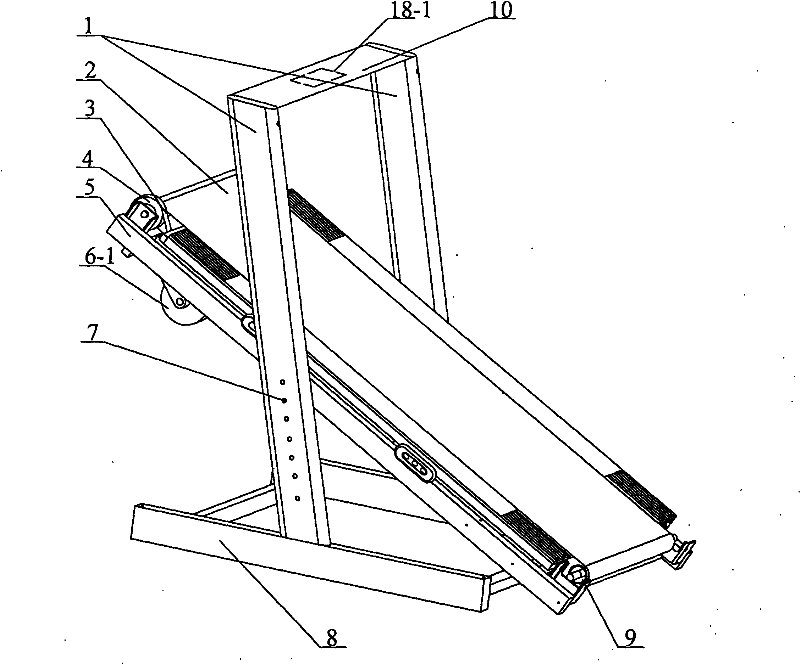
[0026] Such as figure 1 As shown: the treadmill mainly includes a base 8, two uprights 1 fixed on the base 8, an underframe 5 fixed between the two uprights 1, and a running belt 2, the running belt 2 passes through the front roller 4 and the rear roller 9 is installed on the bottom frame 5, and the vertical rod 1 is also provided with a slope adjustment hole 7, and the bottom frame 5 is fixedly connected with the vertical rod 1 through the positioning bolts, and the vertical rod 1 is adjusted by inserting the positioning bolts into different slope adjustment holes 7. Positioning, the slope of the underframe 5 can be adjusted within a certain range as required. The motor 6-1 controlled by the control meter head 10 is installed below the underframe 5, and the speed governor 18-1 for controlling the motor 6-1 is arranged in the control meter head 10, and the output end of the motor 6-1 passes through the transmission device and the forward roll. The shaft 4 is connected, and th...

Embodiment 2

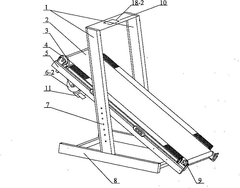
[0030] Such as figure 2 Shown: the bottom of underframe 5 is provided with a driven wheel 6-2, and driven wheel 6-2 is connected with front roller shaft 4 through transmission device, and transmission device is ribbed belt 3, and driven wheel 6-2 adopts metal to make, and its The right side is equipped with electromagnet 11, and electromagnet 11 comprises iron core and coil, is provided with the voltage controller 18-2 that is connected with electromagnet 11 in the control table head 10, after electromagnet is energized, driven wheel 6-2 rotates cutting The magnetic lines of force will generate eddy currents in the driven wheel 6-2, which will generate a magnetic field to resist the rotational force in the direction of rotation of the driven wheel 6-2 itself, and this rotational force will apply reverse rotation to the front roller 4 through the V-ribbed belt 3 force, so as to achieve the purpose of speed regulation. Others are the same as embodiment 1.

[0031] When using ...

Embodiment 3

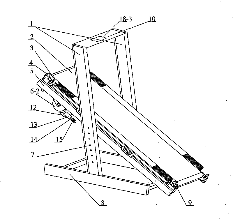
[0035] Such as image 3 Shown: the bottom of the underframe 5 is provided with a driven wheel 6-2, the driven wheel 6-2 is connected with the front roller 4 through a transmission device, the transmission device is a V-ribbed belt 3, and the right side of the driven wheel 6-2 is equipped with a friction The speed regulating device, the friction speed regulating device comprises a brake pad 12, a support 13, a leading screw 14 and a micro servo motor 15. Control meter 10 is provided with forward and reverse controller 18-3 connected with micro servo motor 15, by changing the forward and reverse of micro servo motor 15, the gap between brake pad 12 and driven wheel 6-2 can be adjusted, The frictional force of the brake pad 12 to the driven wheel 6-2 applies a reverse rotational force to the front roller 4 through the V-ribbed belt 3, thereby achieving the purpose of speed regulation. Others are the same as embodiment 1.

[0036] When using this example:

[0037] When the traine...


PUM


Abstract

The invention relates to a speed regulation method for an unpowered treadmill capable of regulating the speed and a treadmill thereof, belonging to the field of aerobic fitness equipment and a speed regulation method thereof. The speed regulation method provided by the invention is characterized in that the front end of a chassis is tilted and is in an inclined shape; after a person stands on a running ribbon, the running ribbon slides downwards and rotates by utilizing the gravity of a human body; and a front rolling shaft or a rear rolling shaft of the running ribbon applies resistance by utilizing a speed regulation device, thereby regulating the rotating speed of the running ribbon. The treadmill provided by the invention is characterized by comprising a treadmill body, wherein the chassis is arranged at the lower part of the treadmill body; the front rolling shaft is arranged at the front end of the chassis, and the rear rolling shaft is arranged at the rear end; the running ribbon is installed on the chassis through the front rolling shaft and the rear rolling shaft; the front end of the chassis is tilted and is in an inclined shape; and the front rolling shaft or the rear rolling shaft is connected with the speed regulation device. The invention has the advantages of flexibility and convenience in use, wide application range, energy conservation and good body building effects.

Description

technical field [0001] The invention relates to a speed regulating method of an adjustable speed non-powered treadmill and the treadmill, belonging to the field of aerobic fitness equipment and the speed regulating method thereof. Background technique [0002] Existing treadmills include mechanical and electric types: Mechanical treadmills are an active running method that does not require an external power source, but its speed changes with the movement speed of the trainer and cannot be adjusted , so the effect of fitness training is not obvious; the electric treadmill is a passive running method, the trainer needs to first set the running speed according to his own physical ability, and forcefully carry out running training at this speed, so the training effect is good, but due to the electric running The treadmill uses a motor to provide power to make the treadmill run at a constant speed, so compared with a mechanical treadmill, it has the disadvantage of large energy c...

Claims


Application Information

Patent Timeline
Patent Type & Authority Applications(China)
IPC IPC(8): A63B22/02A63B24/00
Inventor 李军
Owner SHAN DONG HUIKANG SPORT EQUIP
Why Eureka
Try Eureka