Speed regulation method for unpowered treadmill capable of regulating speed and treadmill thereof
A treadmill and power technology, applied in the field of aerobic fitness equipment and its speed regulation, can solve the problems of low energy consumption, inability to adjust the speed, and inconspicuous fitness training effect, and achieve flexible and convenient use, good fitness effect, and applicable wide range of effects
- Summary
- Abstract
- Description
- Claims
- Application Information
AI Technical Summary
Problems solved by technology
Method used
Image
Examples
Embodiment 1
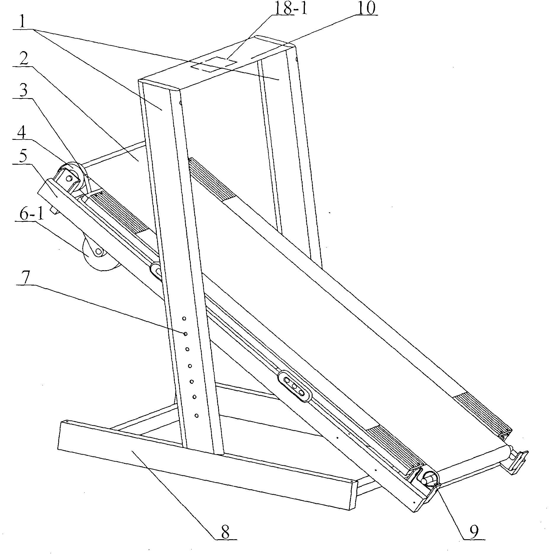
[0026] Such as figure 1 As shown: the treadmill mainly includes a base 8, two uprights 1 fixed on the base 8, an underframe 5 fixed between the two uprights 1, and a running belt 2, the running belt 2 passes through the front roller 4 and the rear roller 9 is installed on the bottom frame 5, and the vertical rod 1 is also provided with a slope adjustment hole 7, and the bottom frame 5 is fixedly connected with the vertical rod 1 through the positioning bolts, and the vertical rod 1 is adjusted by inserting the positioning bolts into different slope adjustment holes 7. Positioning, the slope of the underframe 5 can be adjusted within a certain range as required. The motor 6-1 controlled by the control meter head 10 is installed below the underframe 5, and the speed governor 18-1 for controlling the motor 6-1 is arranged in the control meter head 10, and the output end of the motor 6-1 passes through the transmission device and the forward roll. The shaft 4 is connected, and th...
Embodiment 2
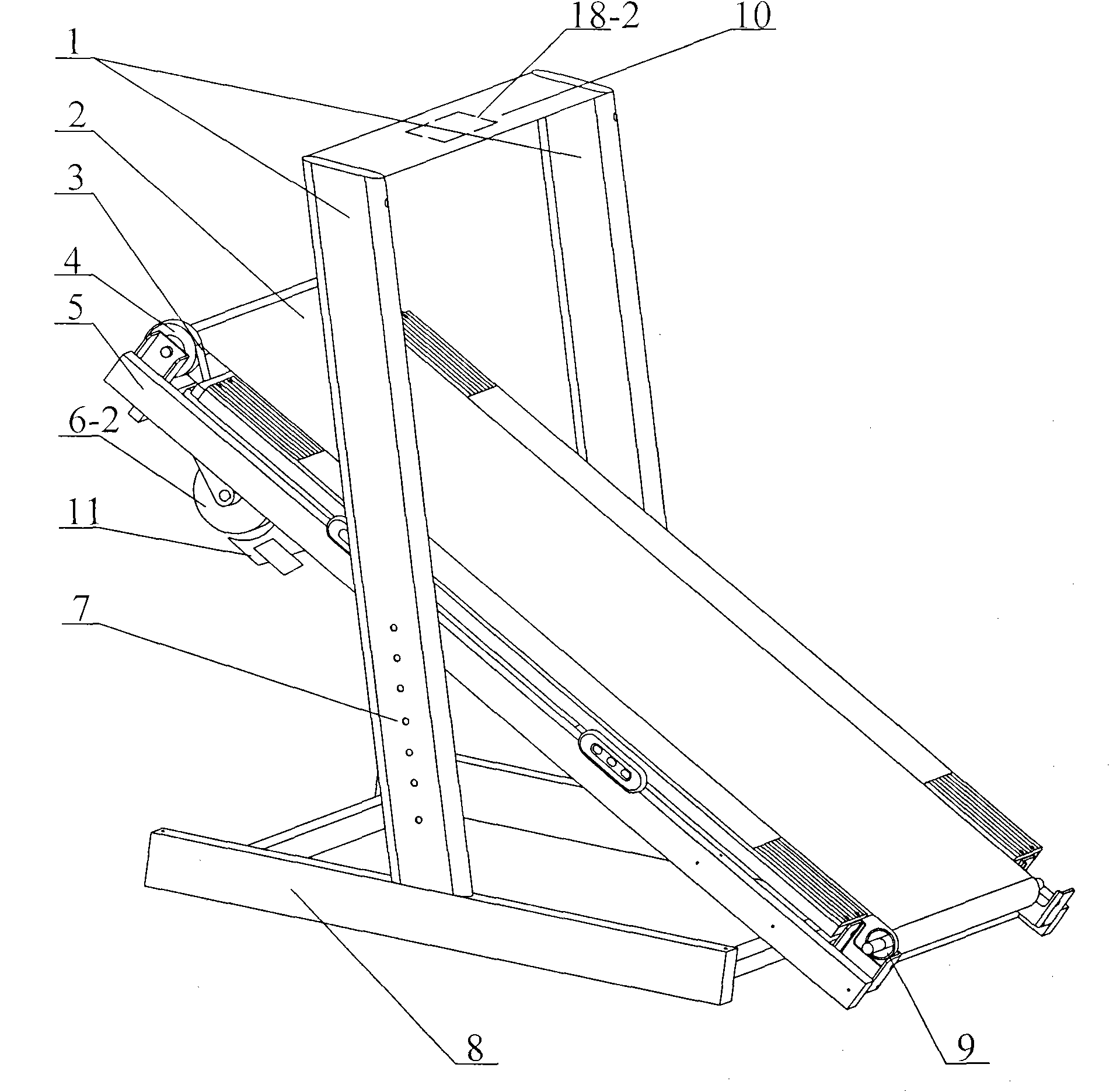
[0030] Such as figure 2 Shown: the bottom of underframe 5 is provided with a driven wheel 6-2, and driven wheel 6-2 is connected with front roller shaft 4 through transmission device, and transmission device is ribbed belt 3, and driven wheel 6-2 adopts metal to make, and its The right side is equipped with electromagnet 11, and electromagnet 11 comprises iron core and coil, is provided with the voltage controller 18-2 that is connected with electromagnet 11 in the control table head 10, after electromagnet is energized, driven wheel 6-2 rotates cutting The magnetic lines of force will generate eddy currents in the driven wheel 6-2, which will generate a magnetic field to resist the rotational force in the direction of rotation of the driven wheel 6-2 itself, and this rotational force will apply reverse rotation to the front roller 4 through the V-ribbed belt 3 force, so as to achieve the purpose of speed regulation. Others are the same as embodiment 1.
[0031] When using ...
Embodiment 3
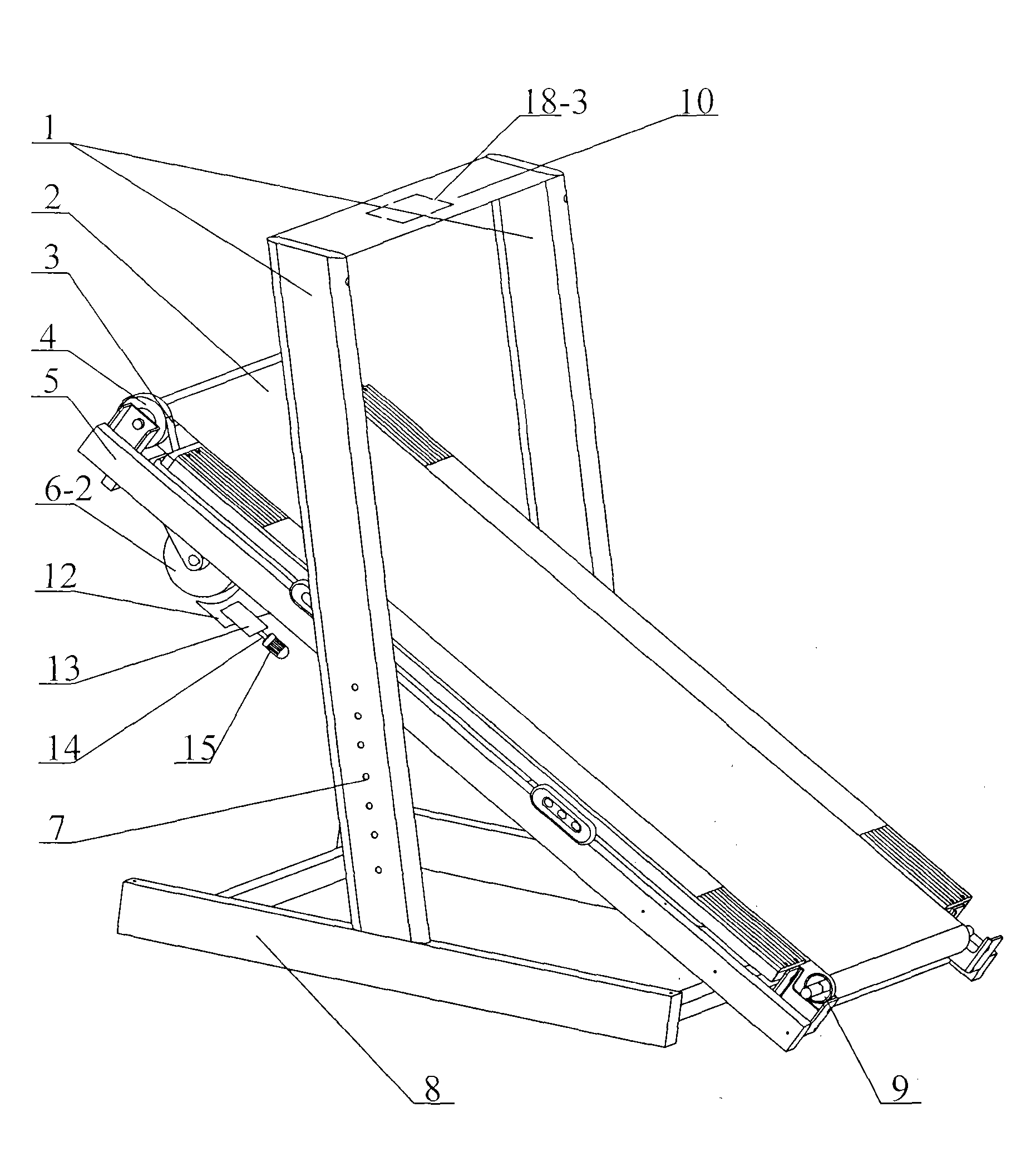
[0035] Such as image 3 Shown: the bottom of the underframe 5 is provided with a driven wheel 6-2, the driven wheel 6-2 is connected with the front roller 4 through a transmission device, the transmission device is a V-ribbed belt 3, and the right side of the driven wheel 6-2 is equipped with a friction The speed regulating device, the friction speed regulating device comprises a brake pad 12, a support 13, a leading screw 14 and a micro servo motor 15. Control meter 10 is provided with forward and reverse controller 18-3 connected with micro servo motor 15, by changing the forward and reverse of micro servo motor 15, the gap between brake pad 12 and driven wheel 6-2 can be adjusted, The frictional force of the brake pad 12 to the driven wheel 6-2 applies a reverse rotational force to the front roller 4 through the V-ribbed belt 3, thereby achieving the purpose of speed regulation. Others are the same as embodiment 1.
[0036] When using this example:
[0037] When the traine...
PUM
 Abstract
Description
Claims
Application Information
 - R&D
- Intellectual Property
- Life Sciences
- Materials
- Tech Scout
- Unparalleled Data Quality
- Higher Quality Content
- 60% Fewer Hallucinations
Browse by: Latest US Patents, China's latest patents, Technical Efficacy Thesaurus, Application Domain, Technology Topic, Popular Technical Reports.
© 2025 PatSnap. All rights reserved.Legal|Privacy policy|Modern Slavery Act Transparency Statement|Sitemap|About US| Contact US: help@patsnap.com


