Iron remover

A technology of iron remover and magnet, which is applied in chemical instruments and methods, magnetic separation, solid separation, etc. It can solve the problems of unsatisfactory iron removal effect, large air magnetic resistance, uneven distribution of magnetic induction lines, etc.

Inactive Publication Date: 2011-11-30
佛山市禅城区仁和变压器厂
View PDF6 Cites 3 Cited by
  • Summary
  • Abstract
  • Description
  • Claims
  • Application Information

AI Technical Summary

Problems solved by technology

[0002] Existing iron removers all use the magnetic field generated by magnets or excitation coils to propagate to the catcher in the air, and the catcher is magnetized to suck away the iron filings or steel debris in the material circulating through it; but the magnetic resistance of the air It is very large, which leads to uneven distrib

Method used


Image

  • Iron remover
  • Iron remover
  • Iron remover

Examples


Embodiment Construction

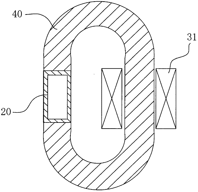
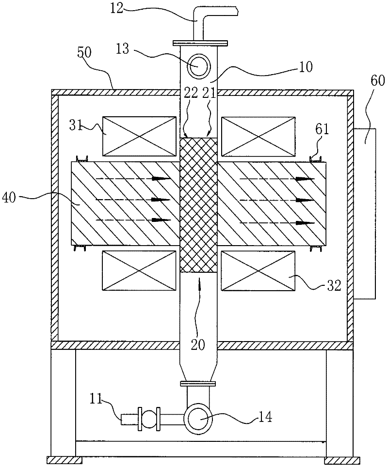
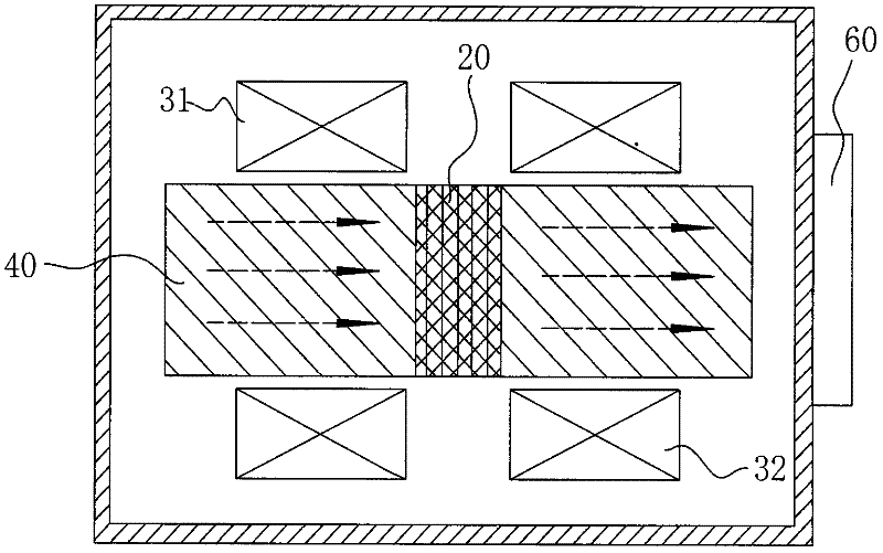
[0009] like figure 1 As shown, an iron remover includes a magnet and a catcher 20 located within the magnetic field of the magnet. The catcher 20 is used to supply the material to circulate and absorb iron filings in the material at the same time, that is, the catcher 20 must first be able to supply the material Circulation, for example, the catcher 20 is a tubular shell; to play the role of being able to absorb and remove iron filings, that is, the material of the catcher 20 should be magnetically conductive, such as iron or steel or pure iron, ferrosilicon, etc. Soft magnetic material; in other words, the catcher 20 is magnetized by the magnetic field of the magnet and has the ability to attract iron. There are many implementations of such a technical solution, which will not be repeated here. The improvement of the present invention is that a low reluctance magnetic conductor 40 is arranged in the magnetic field of the magnet, and the magnetic conductor 40 is arranged alon...


PUM


Abstract

The invention relates to an iron-remover for filtering iron filings or steel chippings in ceramic slurries, comprising a magnet and a trap positioned within the range of the magnetic field of the magnet, wherein the trap is used to allow the circulation of materials and simultaneously absorb and remove the iron filings in the materials. The iron-remover provided by the invention is characterized in that the a magnetizer with low magnetic resistance is disposed within the magnetic field of the magnet and arranged along the direction of magnetic induction lines; the trap is embedded in the magnetizer. The magnetic field within the magnetizer is distributed more uniformly and then the magnetic field within the trap embedded in the magnetizer is distributed uniformly so as to avoid the uneven distribution of magnetic force. In the meanwhile, as the magnetic resistance of the magnetizer is less than that of air, the loss of magnetic force transmitted within the magnetizer by the magnetic field is decreased. Therefore, the trap has a greater intensity of magnetic force to absorb and remove the iron filings as well as a better effect for removing iron. The electric magnetic iron-removing effect of the trap is improved simultaneously from two aspects. Thus, the iron-removing effect of the whole iron-remover is more reliable.

Description

technical field [0001] The invention relates to an iron remover for filtering iron filings or steel debris in ceramic slurry. Background technique [0002] Existing iron removers all use the magnetic field generated by magnets or excitation coils to propagate to the catcher in the air, and the catcher is magnetized to suck away the iron filings or steel debris in the material circulating through it; but the magnetic resistance of the air It is very large, which leads to uneven distribution of magnetic induction lines in the magnetic field, and there is no good magnetic medium circuit. That is to say, the distribution of the magnetic force transmitted from the magnet to the trap is uneven or significantly weakened, so the iron removal effect of the trap will be greatly weakened, and the iron removal effect is not ideal. Contents of the invention [0003] The purpose of the present invention is to provide an iron remover with more reliable iron removal effect. [0004] In ...

Claims


Application Information

Patent Timeline
IPC IPC(8): B03C1/02
Inventor 谭文飞
Owner 佛山市禅城区仁和变压器厂
Why Eureka
Try Eureka