Three-lobed spinneret and spinning components

A spinning assembly and spinneret technology, applied in the field of three-blade spinnerets and spinning assemblies, can solve problems such as unsolvable problems, and achieve the effects of high work efficiency, less heat loss, and easy disassembly and assembly.

Inactive Publication Date: 2011-11-30
CHANGZHOU FANGXING PRECISION MACHINERY
View PDF10 Cites 2 Cited by
  • Summary
  • Abstract
  • Description
  • Claims
  • Application Information

AI Technical Summary

Problems solved by technology

[0004] Although the above-mentioned scheme has improved the performance to a certain extent, it still cannot solve the problems existing in the prior art

Method used


Image

  • Three-lobed spinneret and spinning components
  • Three-lobed spinneret and spinning components
  • Three-lobed spinneret and spinning components

Examples


Embodiment Construction

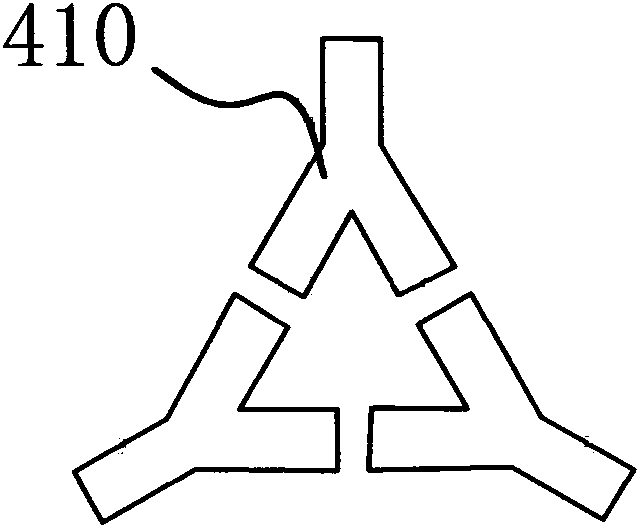
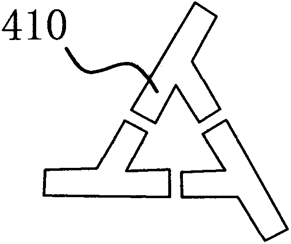
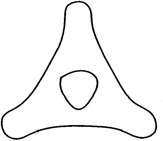
[0019] like figure 1 and 2 As shown, the three-lobed spinneret includes a disc-shaped plate body 40, and a plurality of spinneret holes 41 are provided on the plate body 40, and each spinneret hole 41 includes three injection ports 410 that are enclosed together. The injection port 410 described above is Y-shaped or y-shaped. The fibers produced by the above-mentioned spinneret holes 41 are as follows: image 3 shown.

[0020] like Figure 4 As shown, the three-lobed spinneret spinning assembly is arranged in the spinning box body, including a feed plate 1, a feed port 11 is provided on the side of the feed plate 1, and a feed port 11 is provided at one end of the feed plate 1. The feed port 11 communicates with the feed port 12 . The feed plate 1 is provided with a distribution plate 2 positioned at the discharge port 12, the distribution plate 2 has a number of axially through distribution holes 21 and the distribution plate 2 is fixed on the feed plate 1 through the mi...


PUM


Abstract

The invention belongs to the technical field of fibers and spinning equipment, and in particular relates to a three-leaf spinneret and a spinning assembly. It solves technical problems such as unreasonable design of the prior art. The three-lobed spinneret includes a disc-shaped plate body, on which several spinneret holes are arranged, and each spinneret hole includes three enclosing injection ports, and the injection ports are Y-shaped or y-shaped. The three-lobed spinneret spinning assembly includes a feed plate, which is provided with a distribution plate, which is fixed on the feed plate through an intermediate plate. The spinneret holes penetrate axially and the spinneret plate is fixed on the middle plate through the lower plate. Its advantages are: reasonable design, simple structure, the produced fiber has good bulkiness and rigidity, good standing performance, and has a certain degree of bright effect. Easy to assemble and disassemble, high work efficiency, less heat loss, especially for the spinning assembly used in the test, it is very convenient to replace the spinneret.

Description

technical field [0001] The invention belongs to the technical field of fibers and spinning equipment, and in particular relates to a three-leaf spinneret and a spinning assembly. Background technique [0002] At present, the bulkiness and stiffness of conventional fibers are difficult to guarantee, and it is difficult to obtain good standing performance, and usually do not have a bright effect. In addition, in the prior art, the spinneret and the distribution plate of the chemical fiber spinning assembly are sequentially loaded into the casing from above, and then the feeding plate is covered, and then the entire assembly is transferred into the spinning box. The entire disassembly process is cumbersome. Time-consuming and labor-intensive, seriously affecting work efficiency. When the spinneret needs to be replaced, the entire assembly must be disassembled from the spinning box, and then the chemical fiber spinning assembly must be disassembled for replacement. The whole p...

Claims


Application Information

Patent Timeline
IPC IPC(8): D01D5/253
Inventor 周为民张培杰许建南吴意健盛小平徐明朱建新戴志成吴午大杭海飙汤宇峰金盛毛伟如李梅宏
Owner CHANGZHOU FANGXING PRECISION MACHINERY
Why Eureka
Try Eureka