Continuous oil pipe traction device

A technology of traction device and tubing, which is applied in the direction of drill pipe, casing, drilling equipment, etc., can solve the problems of coiled tubing damage, etc., and achieve the effect of convenient disassembly and simple structure

Active Publication Date: 2014-03-12
SICHUAN HONGHUA PETROLEUM EQUIP
View PDF8 Cites 0 Cited by
  • Summary
  • Abstract
  • Description
  • Claims
  • Application Information

AI Technical Summary

Problems solved by technology

[0003] However, since the coiled tubing is used as the "drill pipe" of the coiled tubing drilling rig, the coiled tubing must be pulled and retrieved at least once when performing coiled tubing drilling operations at each new well location, and the coiled tubing often needs to be disassembled and installed. The method is usually to guide and retract the coiled tubing by using a hoist equipped with a wire rope. In order to ensure a stable connection, the free end of the coiled tubing and the wire rope is usually welded. After guiding to a predetermined area, the welded part is cut. During the pulling process, physical damage will be caused to the coiled tubing

Method used


Image

  • Continuous oil pipe traction device
  • Continuous oil pipe traction device
  • Continuous oil pipe traction device

Examples


Embodiment Construction

[0022] Below in conjunction with accompanying drawing, the present invention is described in detail.

[0023] In order to make the object, technical solution and advantages of the present invention clearer, the present invention will be further described in detail below in conjunction with the accompanying drawings and embodiments. It should be understood that the specific embodiments described here are only used to explain the present invention, not to limit the present invention.

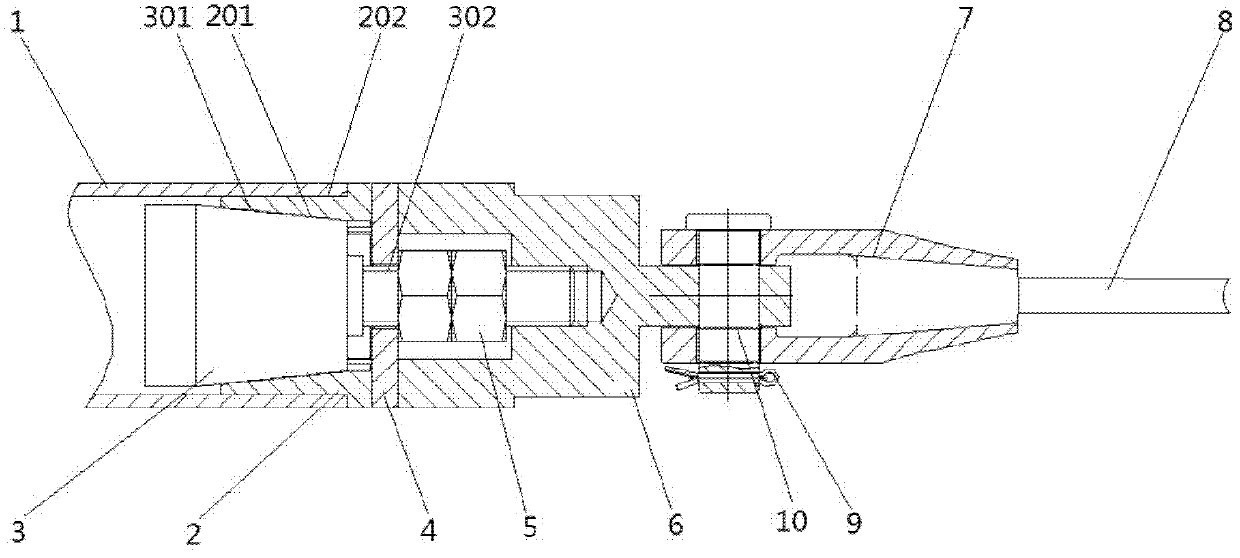
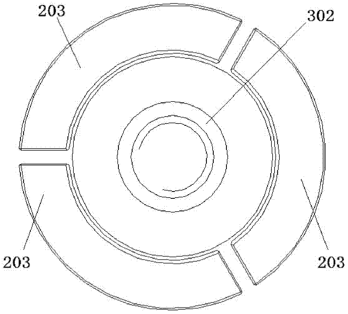
[0024] Such as figure 2 and image 3 As shown, the coiled tubing traction mechanism of the present invention includes an outer tapered sleeve 2 connected to the inner wall of the end of the coiled tubing 1. The outer tapered sleeve 2 is composed of an inner conical surface 201 and an outer cylindrical surface 202. The inner side of the outer tapered sleeve 2 is an inner conical surface 201, the radial direction of the outer taper sleeve 2 is the outer cylindrical surface 202. The outer cylindr...


PUM


Abstract

The invention discloses a continuous oil pipe traction device. The continuous oil pipe traction device comprises a steel wire rope connected with a continuous oil pipe; an inner taper sleeve is arranged in the continuous oil pipe; an outer taper sleeve is arranged between the inner taper sleeve and the inner wall of the continuous oil pipe; the end of the inner taper sleeve is provided with a threaded rod; a nut is arranged on the threaded rod; the nut can compact the inner taper sleeve and the inner taper sleeve; the threaded rod is connected with the steel wire rope detachably; the inner taper sleeve can be utilized for pushing the outer wall of the outer taper sleeve to connect the inner wall of the continuous oil pipe closely by matching the inner taper sleeve and the outer tapper sleeve; by matching the threaded rod and the nut on the inner taper sleeve and the outer taper sleeve, the combination degree of the inner taper sleeve and the outer taper sleeve can be adjusted; and the tightness degree of the outer taper sleeve and the continuous oil pipe can be adjusted according to the tension strength, so that the traction device is connected with the continuous oil pipe closely, simultaneously the continuous oil pipe cannot be damaged physically.

Description

technical field [0001] The invention relates to a drawing device for a pipe body, in particular to a drawing device for a coiled tubing. Background technique [0002] The coiled tubing traction device is mainly used for coiled tubing drilling rigs. The main difference between coiled tubing drilling rigs and conventional oil drilling rigs is that the "drill pipe" of a coiled tubing drilling rig is a continuous section of coiled tubing, usually called "coiled tubing". The drilling rig uses this continuous coiled tubing to connect with the downhole motorized drilling tool and form a mud circulation channel. During the process of coiled tubing drilling, the torque of the drill bit is provided by the downhole motorized drilling tool, and the drilling pressure is determined by the unique force of the coiled tubing drilling rig. Equipment injection head provided. In the non-drilling operation stage, the coiled tubing is usually wound on a reel matched with the coiled tubing rig. B...

Claims


Application Information

Patent Timeline
Patent Type & Authority Patents(China)
IPC IPC(8): E21B19/22
Inventor 姚宇翔
Owner SICHUAN HONGHUA PETROLEUM EQUIP
Why Eureka
Try Eureka