

Method, device and system for network side triggering terminal communication
A technology for terminal communication and communication system, applied in the field of triggering terminal communication on the network side, it can solve the problems of insufficient access resources, network congestion, and inability to fully utilize network idle resources, etc., so as to avoid insufficient resources, improve utilization efficiency, and avoid network The effect of congestion
- Summary
- Abstract
- Description
- Claims
- Application Information
AI Technical Summary
Problems solved by technology
Method used
Image

Examples
Embodiment 1
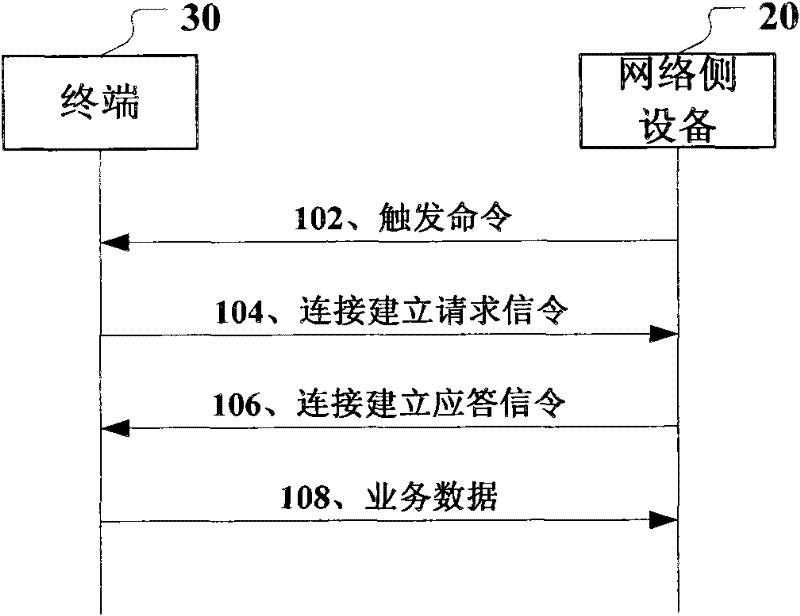
[0027] Such as figure 1 As shown, the embodiment flow of the method for triggering terminal communication on the network side of the present invention mainly includes the following steps:
[0028] Step 102, the network side device generates a trigger command and sends it to the terminal,
[0029] Step 104, the terminal establishes a connection with the network side according to the received trigger command, and sends a connection establishment request signaling to the network side device;
[0030] Step 106, the network side device sends a connection establishment response message to the terminal through the connection establishment request;
[0031] Step 108, after the connection is successfully established, the terminal uploads service data to the network side.
[0032] In this embodiment, the trigger command can be sent to the terminal in the following three ways, and these three situations are described in detail below:
[0033] (1) The trigger command is located in the ...
Embodiment 2
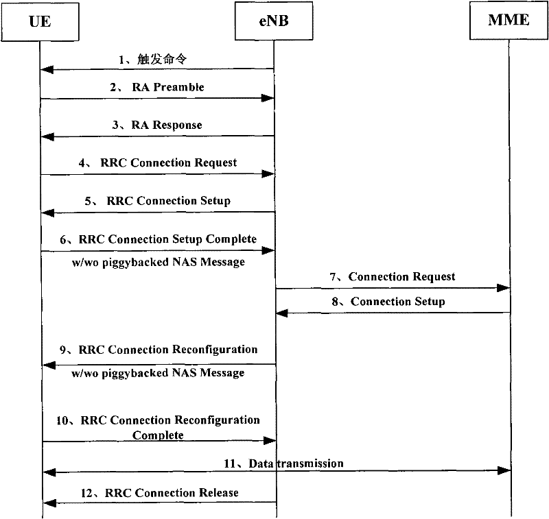
[0046] Taking the LTE system as an example, figure 2 It is a specific process of another embodiment of the method for triggering terminal communication on the network side when the terminal is a UE and the network-side device is an eNB in this embodiment. Such as figure 2 As shown, the main steps are as follows:
[0047] 1. The eNB sends a trigger command to the UE to trigger the UE to start communication;
[0048] 2. The UE uses MSG1 signaling to send a random access preamble (RA preamble) to the eNB to let the eNB know that there is a terminal trying to establish a connection with the base station;
[0049] 3. The eNB allocates corresponding resources according to the confirmed preamble and sends a random access response message (RA Response) to the UE with MSG2 signaling, carrying a time-advance message and allocated uplink resources;
[0050] 4. The UE sends an RRC connection establishment request (Radio Resource ControlRequest) to the eNB with MSG3 signaling, and s...
PUM
 Abstract
Description
Claims
Application Information