
Gripper

A clamping jaw and body technology, which is applied in the field of clamping devices for clamping multi-cavity injection molded parts, can solve the problems of low demoulding quality, fracture, and deformation of molded parts, and achieve the effect of improving the demoulding quality

Inactive Publication Date: 2011-12-07
HONG FU JIN PRECISION IND (SHENZHEN) CO LTD +1
View PDF6 Cites 4 Cited by
  • Summary
  • Abstract
  • Description
  • Claims
  • Application Information

AI Technical Summary

Problems solved by technology

However, if the adhesive force between the molded part and the mold is large, the stripping of the material rod clamping the molded part may cause the deformation or breakage of the connecting rod (formed in the runner (runner) of the mold) of the molded part, making the entire molding Parts are deformed or the molded parts cannot be completely demoulded, and the demoulding quality is low

Method used


Image

  • Gripper
  • Gripper
  • Gripper

Examples


Embodiment Construction

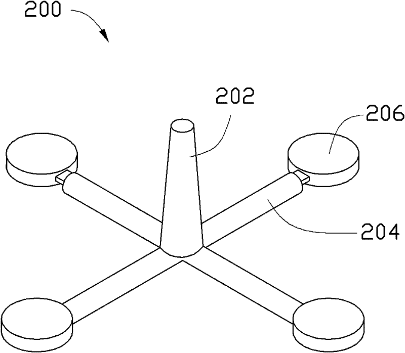
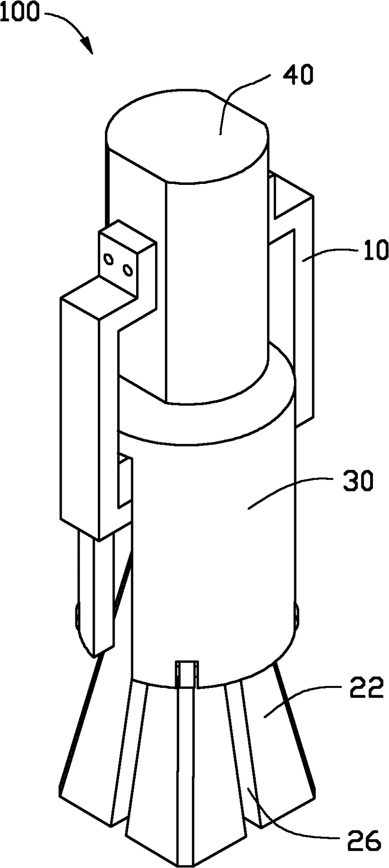
[0050] see Figure 1 to Figure 4 , the clamping device 100 of the preferred embodiment of the present invention is used to clamp a four-cavity lens forming part 200 for demoulding. The lens forming part 200 includes a material rod 202, four connecting rods 204 extending radially and equiangularly (90°) from the end of the material rod 202 and four lenses 206 ( Formed in the cavity (cavity) of the mold (not shown in the figure).

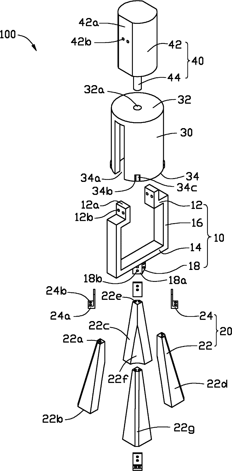
[0051] The clamping device 100 includes a fixed frame 10 , a plurality of jaws 20 , a sleeve 30 and a linear driving device 40 . Each jaw 20 includes a jaw body 22 and an elastic element 24 for fixing the jaw body 22 to the fixed frame 10 . A plurality of jaw bodies 22 are distributed in bundles. A gap 26 for accommodating a corresponding connecting rod 204 exists between every two adjacent jaw bodies 22 . The sleeve 30 is inserted into the plurality of jaw bodies 22 from one side of the plurality of elastic elements 24 and constrains the pluralit...


PUM


Abstract

The invention provides a gripping device for clamping and taking out multicavity injected shaped parts. The shaped part comprises a material rod and a connecting rod formed by extended ends of a plurality of material rods. The gripping device comprises a fixed framework, a plurality of gripping jaws, a sleeve and a linear drive unit. Each gripping jaw comprises a gripping jaw body and an elastic element which fixes the gripping jaw body on the fixed framework. The plurality of gripping jaw bodies are distributed in a bunchy shape. A gap for accommodating a corresponding connecting rod is located between every two adjacent gripping jaw bodies. The sleeve is sleeved around the gripping jaw bodies from the end where a plurality of elastic elements are located, and constrains the gripping jaw bodies. The linear drive unit is fixed on the fixed framework for driving the sleeve to move towards a direction far from the elastic elements and to reset. The gripping device provided in the invention clamps and takes out shaped parts through a plurality of connecting rods so as to realize demoulding, which enables deformation or fracture of the connecting rods to be avoided and quality of demoulding to be improved.

Description

technical field [0001] The invention relates to a clamping device, in particular to a clamping device for clamping multi-cavity injection molded parts. Background technique [0002] At present, multi-cavity injection molded parts can be clamped and demolded by clamping devices. The existing gripping device is generally a two-jaw type gripping device, which can only grip rod-shaped objects. Therefore, currently, the material rod (formed in the sprue of the mold) of the molded part is usually clamped by a two-jaw type clamping device to demould the molded part. However, if the adhesive force between the molded part and the mold is large, the stripping of the material rod clamping the molded part may cause the deformation or breakage of the connecting rod (formed in the runner (runner) of the mold) of the molded part, making the entire molding Parts are deformed or the molded parts cannot be completely demoulded, and the demoulding quality is low. Contents of the invention ...

Claims


Application Information

Patent Timeline
Patent Type & Authority Applications(China)
IPC IPC(8): B29C45/40
Inventor 黄建峰
Owner HONG FU JIN PRECISION IND (SHENZHEN) CO LTD
Learn More