energy saving lamps

A technology for lamps and heat sinks, applied in lighting devices, cooling/heating devices of lighting devices, light sources, etc., can solve problems such as lack of use, impact on life, and light decay of LED lamps 13

Inactive Publication Date: 2011-12-07
YADENT
View PDF4 Cites 11 Cited by
  • Summary
  • Abstract
  • Description
  • Claims
  • Application Information

AI Technical Summary

Problems solved by technology

[0003] Although the above-mentioned lamp 1 can achieve lighting effects, there are still shortcomings in use, because when the lamp 1 is used for lighting, its components will generate heat, especially the LED lamp 13, the upright circuit board 12, and the driving circuit board 11. Light bulbs with low wattage, such as Christmas light bulbs, do not pay attention to overall lighting and do not require a long service life, so the heat generated by them is not much, and the heat dissipation requirements are not high
But if the above-mentioned lamp 1 is to achieve the lighting effect that can directly replace the traditional light bulbs on the market, a sufficient number of LED lamps 13 must be arranged inside the lamp 1. Of course, the heat generated by it must be able to be dissipated sufficiently, otherwise the LED lamp 13 will easily cause light decay due to overheating, thereby shortening the service life of the LED lamp 13. Similarly, other components will also affect the service life due to overheating
[0004] This shows that above-mentioned existing light fixture obviously still has inconvenience and defect in structure and use, and urgently needs to be further improved
In order to solve the above-mentioned problems, the relevant manufacturers have tried their best to find a solution, but for a long time no suitable design has been developed, and the general product has no suitable structure to solve the above-mentioned problems. This is obviously the relevant industry. Urgent problem

Method used


Image

  • energy saving lamps
  • energy saving lamps
  • energy saving lamps

Examples


Embodiment Construction

[0032] In order to further explain the technical means and effects of the present invention to achieve the intended purpose of the invention, the specific implementation, structure, features and effects of the energy-saving lamps proposed according to the present invention will be described in detail below in conjunction with the accompanying drawings and preferred embodiments. The description is as follows.

[0033] The aforementioned and other technical contents, features and effects of the present invention will be clearly presented in the following detailed description of preferred embodiments with reference to the drawings. For convenience of description, in the following embodiments, the same elements are denoted by the same numbers.

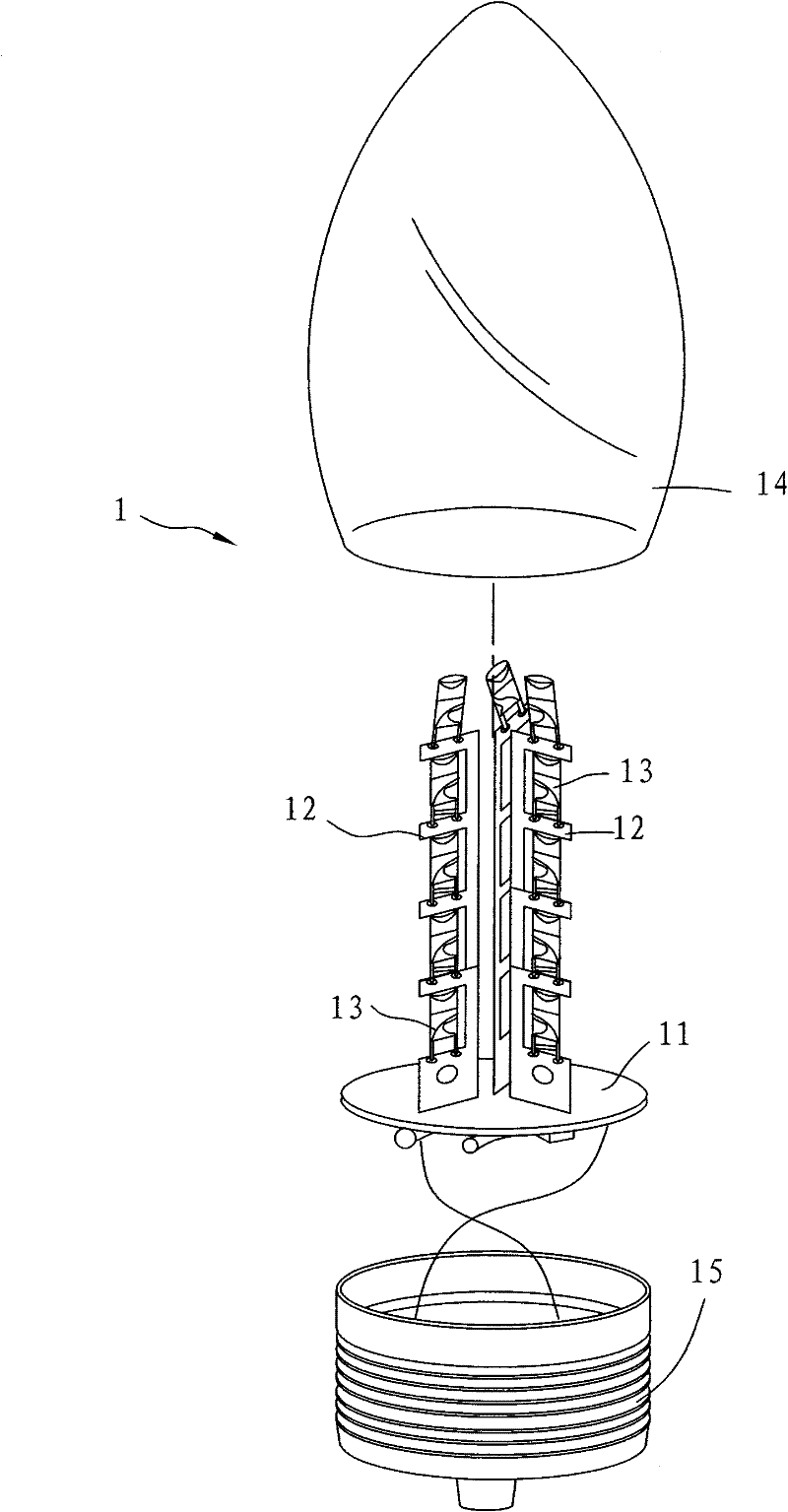
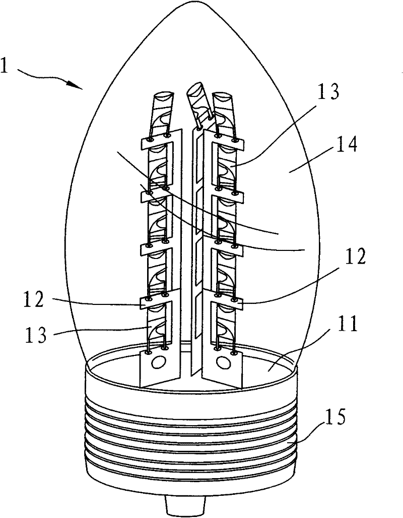
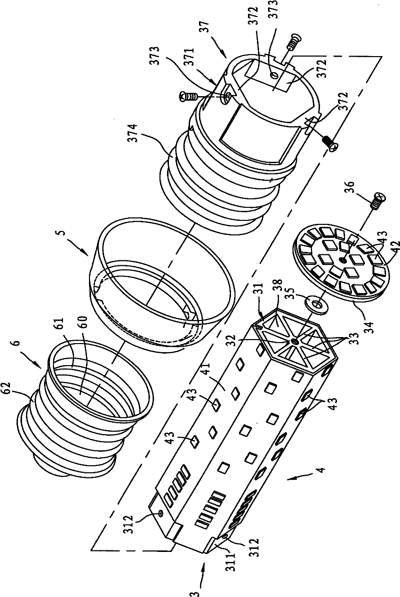
[0034] see image 3 , Figure 4 , Figure 5 as shown, image 3 It is an exploded perspective view of some components of a first preferred embodiment of the energy-saving lamp of the present invention, Figure 4is an exploded cross-sec...


PUM


Abstract

The invention relates to an energy-saving lamp which comprises a shade shell, a heat-dissipating unit and an illuminating unit, wherein the heat-dissipating unit comprises a first heat-dissipating component installed in the shade shell, a second heat-dissipating component arranged in the first heat-dissipating component and an end part heat-dissipating component installed on one end far away fromthe shade shell, of an opening of the second heat-dissipating component, the first heat-dissipating component and the second heat-dissipating component jointly define a heat-dissipating space; and the illuminating unit comprises at least one circuit board arranged outside the first heat-dissipating component and the end part heat-dissipating component, and multiple illuminating components respectively arranged on the circuit board. Through installing the heat-dissipating unit, heat energy of the illuminating unit can be transmitted and dissipated outside; and meanwhile, the heat-dissipating unit has a better heat-dissipating effect, can slow down the light decline of the illuminating components and prolongs the service life of the lamp.

Description

technical field [0001] The invention relates to a lamp, in particular to an energy-saving lamp which can be used for indoor or outdoor lighting. Background technique [0002] In addition to long strip fluorescent tubes, general lighting fixtures also include bulbs, recessed lights, etc. that can be directly screwed to a power socket, etc., please refer to figure 1 , figure 2 as shown, figure 1 is an exploded perspective view of a known lamp, figure 2 It is a three-dimensional view of the combined structure of the lamp. It is a lamp 1 disclosed in Taiwan Patent No. M377525, which includes a horizontal drive circuit board 11 with a plurality of electronic components on the bottom, a plurality of vertical circuit boards 12 arranged on the drive circuit board 11, A plurality of LED lamps 13 arranged on the upright circuit board 12, a lampshade 14 covering the above-mentioned components, and an electric screw head 15 arranged at the bottom of the lampshade 14 and the drivin...

Claims


Application Information

Patent Timeline
Patent Type & Authority Applications(China)
IPC IPC(8): F21S2/00F21V19/00F21V29/00F21V17/00F21Y101/02F21V29/50
Inventor 大木勇
Owner YADENT
Why Eureka
Try Eureka