
display device

A display device and display unit technology, applied in nonlinear optics, instruments, optics, etc., can solve the problems that users cannot adjust the area ratio of the display area and the mirror area by themselves, and the display quality of the display decreases, so as to avoid slow moving speed, Easy electric field change, easy to control effect

Inactive Publication Date: 2011-12-07
CPT TECH GRP +1
View PDF6 Cites 1 Cited by
  • Summary
  • Abstract
  • Description
  • Claims
  • Application Information

AI Technical Summary

Problems solved by technology

However, in this design, the area ratio of the display area to the mirror area is fixed, so the user cannot adjust the area ratio of the display area to the mirror area according to the needs.
Furthermore, since the light emitted by the backlight module needs to pass through an additional polarizer, it will lead to a decrease in the display quality of the overall display.

Method used


Image

  • display device
  • display device
  • display device

Examples


Embodiment Construction

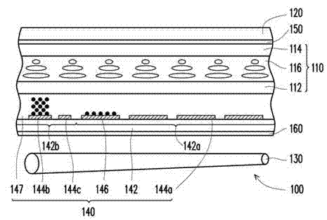
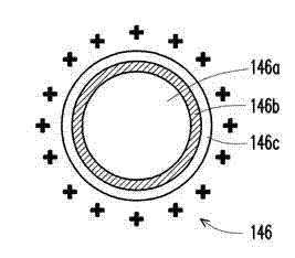
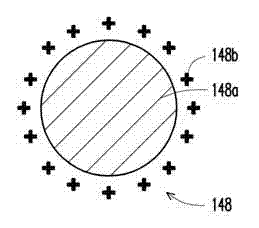
[0058] Figure 1A It is a schematic cross-sectional view of a display device according to an embodiment of the present invention. Figure 1B for Figure 1A An enlarged schematic diagram of a charged particle of an embodiment of FIG. Figure 1C for Figure 1A An enlarged schematic diagram of a charged particle of another embodiment of . Please refer to Figure 1A , in this embodiment, the display device 100 includes a display unit 110 , a touch unit 120 , a backlight unit 130 and an electrophoretic unit 140 . Wherein, the touch unit 120 is disposed above the display unit 110 , the backlight unit 130 is disposed below the display unit 110 , and the electrophoretic unit 140 is disposed between the display unit 110 and the backlight unit 130 .

[0059]In detail, the touch unit 120 is, for example, a resistive touch panel, a capacitive touch panel, an optical touch panel, an acoustic wave touch panel or an electromagnetic touch panel. No restrictions are imposed. The display uni...


PUM

PropertyMeasurementUnit
particle diameteraaaaaaaaaa

Abstract

The invention relates to a display device, which comprises a display unit, a touch control unit, a backlight unit and an electrophoresis unit, wherein the touch control unit is arranged above the display unit; the backlight unit is arranged below the display unit; the electrophoresis unit is arranged on the display unit and comprises a substrate, a plurality of display electrodes, at least one storage electrode, a gate electrode and a plurality of charged particles; the substrate is provided with an active area and a surrounding area; the display electrodes are arranged in the active area of the substrate at equal intervals; the storage electrode is arranged in the surrounding area of the substrate; the gate electrode is arranged in the surrounding area of the substrate and between the display electrodes and the storage electrode; and the charged particles are arranged on the substrate and have the characteristic of mirror reflection.

Description

technical field [0001] The present invention relates to a display device, and in particular to a display device with specular reflection function. Background technique [0002] With the development of technology, digital tools such as mobile phones, digital cameras, digital video cameras, notebook computers and desktop computers are all moving towards more convenient and multi-functional And beautiful direction development. When using these information products, the display panel is an indispensable human-machine communication interface. Through the display function of the display panel, the user can operate the product more conveniently. [0003] In terms of practicability, if the display panel can add the effect of specular reflection, it will surely expand the application range of the display. At present, US Pat. No. 7,636,195 proposes to use a mirror with a polarizing effect (that is, a polarizer) in a display so that the display can simultaneously provide display and ...

Claims


Application Information

Patent Timeline
Patent Type & Authority Applications(China)
IPC IPC(8): G02F1/167
Inventor 陈文政
Owner CPT TECH GRP
Learn More