Supercharge Your Innovation With Domain-Expert AI Agents!

Liquid pressure transmission engine and driving method thereof

A pressure and engine technology, applied in the field of liquid pressure transmission engine and its drive, can solve the problems of high cost, inability to attract consumers' willingness to buy, and users' troubles in use.

Inactive Publication Date: 2014-11-12
翁新壬
View PDF3 Cites 0 Cited by
  • Summary
  • Abstract
  • Description
  • Claims
  • Application Information

AI Technical Summary

Problems solved by technology

[0003] Although there are more environmentally friendly gas engines or electric engines on the market, gas engines and electric engines still have their shortcomings. First of all, gas filling stations and charging stations are not as popular as gas stations, resulting in the use of gas engines or electric engines. The latter has troubles in use; in addition, vehicles with gas engines or electric engines are relatively expensive and cannot attract consumers' willingness to purchase; moreover, the power output of gas engines and electric engines is often lower than that of internal combustion engines , so that gas engines and electric engines can only be used for devices that require only a small amount of power to drive
[0004] To sum up the above, internal combustion engine, gas engine or electric engine all have defects in its use, but many inventors or enterprise research and development can not break away from the framework of the aforementioned engines. For example, a car with an internal combustion engine is only It can be driven at or below 600 psi, but the existing booster devices, such as booster motors or booster pumps, can output continuous high pressure and continuous thrust from 0 to 60,000 psi according to demand, and even worse Some manufacturers can even design the output of the booster device to a continuous high pressure and continuous thrust of more than 60,000 to 100,000 psi according to the needs of customers, but no one can think about how to apply the booster device to the power output. Nowadays, various types of high-pressure pumps or booster pumps and other devices based on the principle of mechanical boosting are known to have the ability to cut steel and other metals, and they must also have the ability to drive tools far beyond the kinetic energy. Therefore, the above-mentioned engines or Every situation has its room for improvement and invention

Method used


Image

  • Liquid pressure transmission engine and driving method thereof
  • Liquid pressure transmission engine and driving method thereof
  • Liquid pressure transmission engine and driving method thereof

Examples


Embodiment Construction

[0032] The implementation of the present invention is described below with reference to specific examples, and those skilled in the art can easily understand other advantages and effects of the present invention from the content disclosed in this specification.

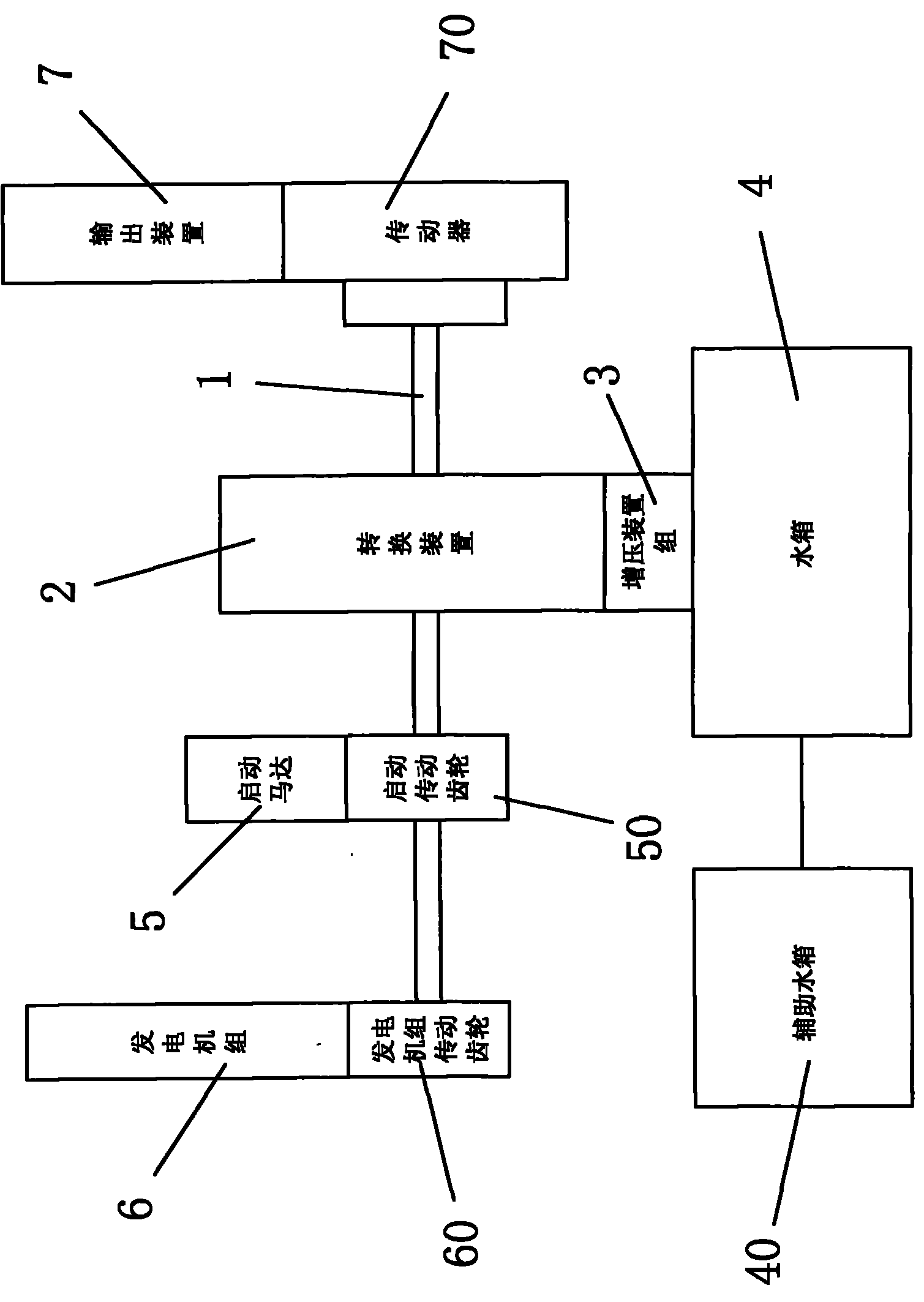
[0033] The present invention provides a driving method of a hydraulic pressure transmission engine, which includes the following steps:

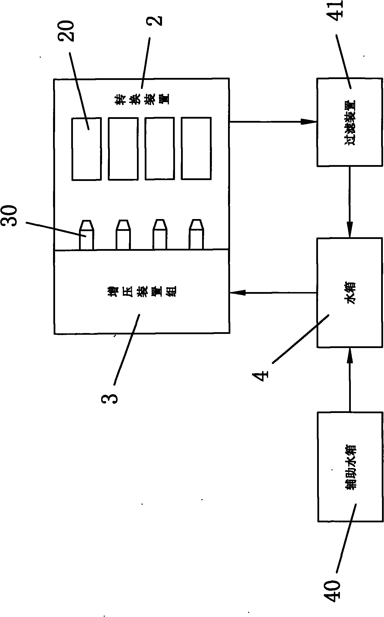
[0034] A. Pressurize the liquid into one of high-pressure liquid or ultra-high-pressure liquid, and then spray the pressurized liquid into a conversion device. For example, for the general industry, if the liquid pressure exceeds 200psi, it can be regarded as high pressure A liquid, if the pressure of the liquid exceeds 20,000 to 30,000 psi or more, it is an ultra-high pressure liquid.

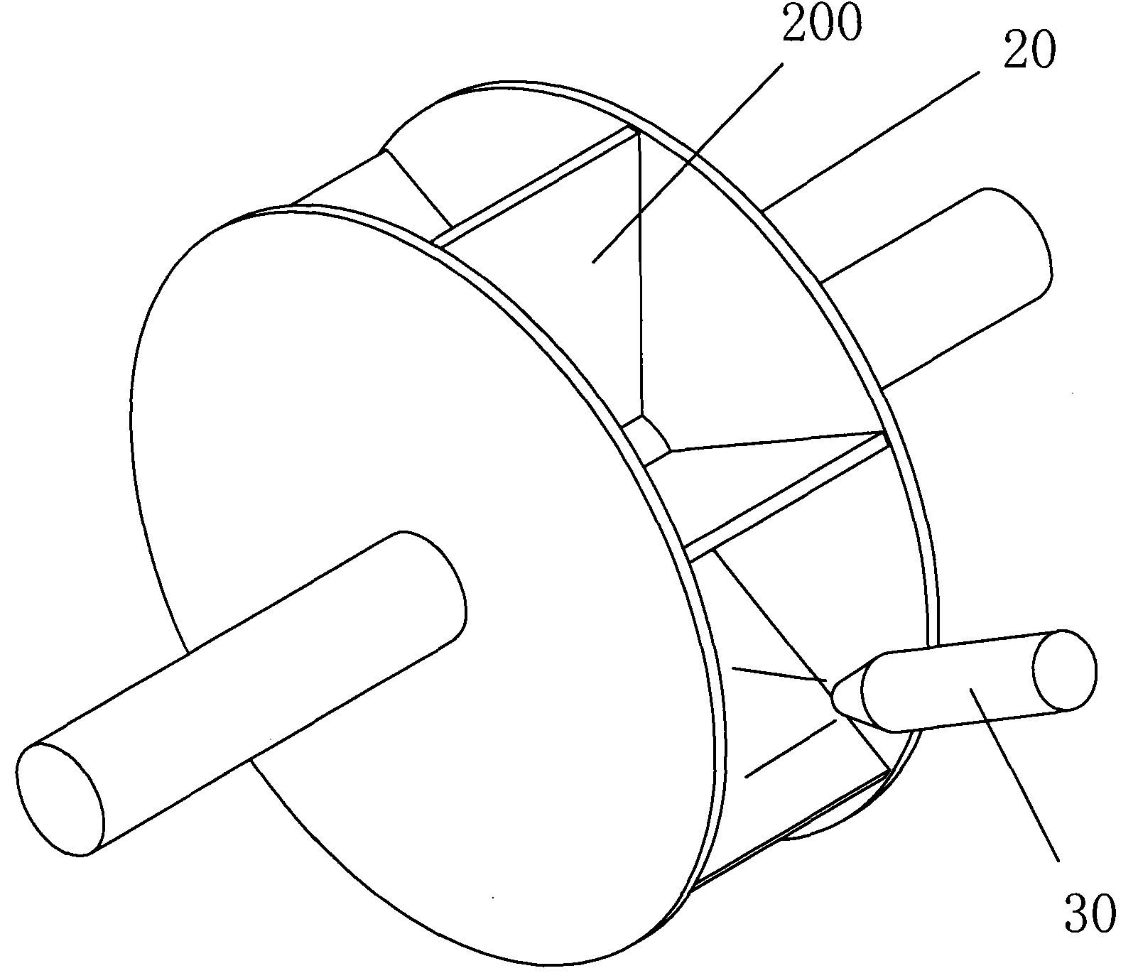
[0035] B. The conversion device converts the pressure of the injected pressurized liquid into power and outputs it.

[0036] C. The power can drive a device equipped with a hydraulic pressure trans...


PUM


Abstract

A liquid pressure driving engine and a driving method thereof are provided. The liquid in a water tank (4) is boosted to be high pressure liquid or super high pressure liquid by a boosting device group (2), and then the boosted liquid is jetted into a conversion device (3). The conversion device converts the pressure of the boosted liquid into power and outputs the power via an output device (7) to drive the equipment assembled with the liquid pressure driving engine, such as an aircraft, a ship, a wheeled vehicle or a tracklaying vehicle, etc. The engine and driving method thereof can reduce the requirement of conventional fuel, even prevent the conventional fuel from being utilized by people any more, so as to achieve the purpose of saving energy, reducing carbon emissions and protecting the environment.

Description

technical field [0001] The invention relates to a liquid pressure transmission engine and its driving method, which converts the pressure of high-pressure liquid into power and electricity, so as to reduce the consumption of petrochemical fuel, gas, vapor fuel, bio-alcohol, bio-gasoline, bio-diesel, etc. The demand for traditional fuels makes them no longer used by people, and then achieves the effects of energy saving, carbon reduction and environmental protection. Background technique [0002] Since petroleum has been widely used, internal combustion engines can be found in almost all kinds of transportation vehicles, such as aircraft, ships, wheeled vehicles or tracked vehicles. However, with the rising awareness of environmental protection, the environmental problems caused by internal combustion engines It has also surfaced, so how to eliminate the internal combustion engine and replace it with a more environmentally friendly device has become an important issue. [00...

Claims


Application Information

Patent Timeline
Patent Type & Authority Patents(China)
IPC IPC(8): F03C2/00
CPCF05B2240/931F05B2240/941F16H41/02B62K2202/00Y02E10/223B62M19/00F03B1/00Y02E10/20
Inventor 翁新壬
Owner 翁新壬
Features
  • R&D
  • Intellectual Property
  • Life Sciences
  • Materials
  • Tech Scout
  • Unparalleled Data Quality
  • Higher Quality Content
  • 60% Fewer Hallucinations
Learn More