Liquid Line Evacuation Antifreeze

A technology of antifreeze device and liquid pipeline, which is applied in the direction of valve device, heating device, solar heat device, etc., to achieve the effect of reliable operation, convenient and practical control, and simple structure

Inactive Publication Date: 2011-12-14
丁文信
View PDF5 Cites 5 Cited by
  • Summary
  • Abstract
  • Description
  • Claims
  • Application Information

AI Technical Summary

Problems solved by technology

[0003] In order to overcome the shortcomings of the existing pipeline emptying valve, the present invention proposes a liquid pipeline emptying antifreeze device

Method used


Image

  • Liquid Line Evacuation Antifreeze
  • Liquid Line Evacuation Antifreeze
  • Liquid Line Evacuation Antifreeze

Examples


Embodiment Construction

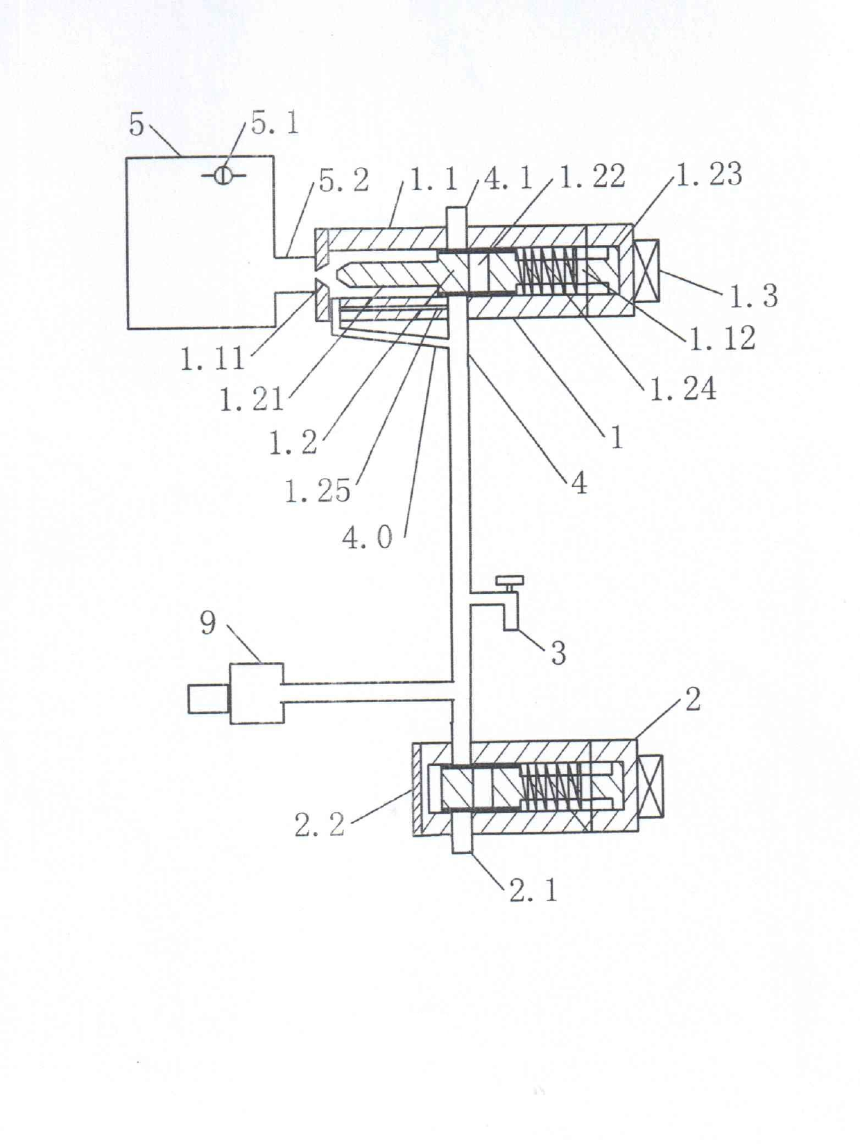
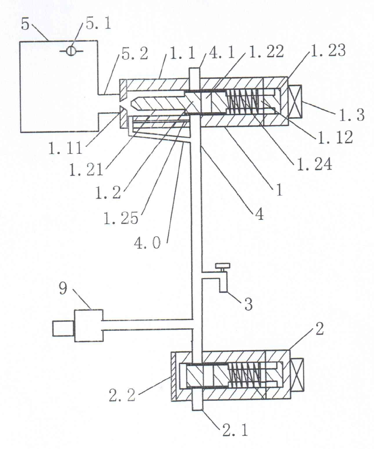
[0013] according to figure 1 As shown, the upper end of the water pipe is connected with a water injection and discharge solenoid valve 1, one side of which is connected to the water container 5 through a connecting pipe 5.2, a water level sensor switch 5.1 is installed in the water container, and the water injection and discharge solenoid valve is installed at the lower end through a water pipe 4. Water discharge solenoid valve 2 is arranged, and water discharge nozzle 3 is installed on the water pipe, and water supply solenoid valve 9 is installed by running water pipe on the water pipe between the water discharge solenoid valve and the water filling water discharge solenoid valve.

[0014] The structure of the water injection and discharge solenoid valve is: the valve body 1.1 of the water injection and discharge solenoid valve is a tubular structure, a valve seat 1.11 is arranged at the connecting pipe end, an electromagnetic driver 1.3 is installed at the other end of the ...


PUM


Abstract

The invention provides a liquid pipeline emptying anti-freezing device. A water injection and drainage electromagnetic valve is arranged at the upper end of a water pipe, a drainage electromagnetic valve is arranged at the lower end of the water pipe, a water supply electromagnetic valve is arranged on the water pipe between the drainage electromagnetic valve and the water injection and drainage electromagnetic valve through a tap water pipe, and a drainage nozzle is arranged on the water pipe. The water injection and drainage electromagnetic valve and the drainage electromagnetic valve are controlled through a drainage electric switch and a water injection electric switch. Because the water injection and drainage electromagnetic valve and the drainage electromagnetic valve are arranged at the upper end and the lower end of the water pipe respectively, an emptying pipe can be communicated with a drainage pipe by the actions of the electromagnetic valves, accumulated water in the waterpipe is drained, and the water pipe is prevented from being frozen. The device has the characteristics of simple structure, reliable operation, convenience, practicability and convenience for control. The device is suitable to be installed in a solar water heater or other device for injecting and draining anti-freezing liquid.

Description

technical field [0001] The invention proposes a device in the field of automatic control, in particular a liquid pipeline emptying antifreeze device. Background technique [0002] Before the present invention was proposed, taking the solar water heater as an example, the problem of antifreezing of water pipes was solved by winding electric heating tape on the pipeline connected with the water storage device installed on the roof of the building. The disadvantage is that it wastes electric energy, and it is also easy to cause safety accidents such as fire and electric leakage. Another way to make the water pipe antifreeze is to manually open the vent valve located on the upper water pipe to let off the water in the water pipe, thereby avoiding the occurrence of freezing of the water pipe and causing the water pipe to freeze. The disadvantages are that when the water pipe needs to be emptied, people need to go up to a high place, which is unsafe, cumbersome and inconvenient t...

Claims


Application Information

Patent Timeline
Patent Type & Authority Applications(China)
IPC IPC(8): F16K11/22F16K31/06F24J2/46
CPCY02E10/40
Inventor 丁文信
Owner 丁文信
Why Eureka
Try Eureka