Live working insulator replacement tool for self-locking conductors with rear tension clamps

A technology of tension-resistant clamps and live work, which is applied in the direction of overhead lines/cable equipment, etc., can solve the problems of broken transmission lines, low operation safety, and no value, and achieves low manufacturing costs, convenient operation, and easy promotion and application Effect

Inactive Publication Date: 2011-12-14
STATE GRID CORP OF CHINA +1
View PDF4 Cites 7 Cited by
  • Summary
  • Abstract
  • Description
  • Claims
  • Application Information

AI Technical Summary

Problems solved by technology

[0002] At present, in the ultra-high voltage power transmission and transformation industry, there are great potential safety hazards in the process of using existing tools to replace line insulator strings
The main reason is that it needs at least two workers to cooperate to replace the insulator string with the existing tools, and, because the installation position of the insulator is that one end of the insulator is close to the wire tower, and the other end is installed away from the wire tower, therefore, at least one One worker has to work at heights while completely leaving the wire tower and the whole body is suspended on the power transmission line. The safety of the operation is low, and the power transmission line is prone to breakage, resulting in accidents of high falls and casualties.
Using automated replacement tools to replace manual labor is the preferred method to solve high-altitude operations, but because existing automated replacement tools are difficult to automatically lock insulators, they have no practical value

Method used


Image

  • Live working insulator replacement tool for self-locking conductors with rear tension clamps
  • Live working insulator replacement tool for self-locking conductors with rear tension clamps
  • Live working insulator replacement tool for self-locking conductors with rear tension clamps

Examples


Embodiment Construction

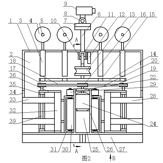
[0009] The live working insulator replacement tool for the self-locking wire of the post-tension clamp according to the present invention, such as figure 2 As shown, it includes a housing 1, an inner chamber 2 is provided in the housing 1, four first buffer rods 3 are fixedly installed on the upper part of the inner chamber 2, and the first guide rod 66 of each first buffer rod 3 extends out of the housing. 1 travel motor 40 is installed outside, and travel sheave 4 is installed on the output shaft of travel motor 40. For convenience, the replacement insulator tool is suspended on the overhead line by the walking sheave 4, such as Figure 5 and Figure 6 As shown, all the running sheaves 4 are located at the front top of the housing 1. Such as figure 2 As shown, the lower part of the inner cavity 2 is symmetrically installed with two barrier-crossing brackets 28 with the central axis of the inner cavity 2 as the midline. Such as figure 2 and Figure 6 Shown, each stra...


PUM


Abstract

The invention discloses a self-locking type live-line work insulator replacing tool with a back strain clamp for a wire. The self-locking type live-line work insulator replacing tool comprises a traveling mechanism, a transversely moving mechanism is arranged at the back of a shell of the traveling mechanism, a transversely moving seat of the transversely moving mechanism is provided with a rotating mechanism, a regulating mechanism is arranged on the rotating mechanism, a turnover articulating seat is arranged at the front end of a rotating rod of the regulating mechanism, a turnover drive motor is arranged on the turnover articulating seat, and the back strain clamp of the insulator replacing tool is provided with a locking mechanism; the locking mechanism is formed by connecting two clamp boards, an electrically operated push rod, a door-shaped press block, inclined blocks, a tension spring and pressing plates; the two clamp boards are arranged at the back of the insulator replacing tool in parallel; cavities in the back strain clamp and the clamp boards are communicated to form a cavity, the electrically operated push rod is arranged in the cavity, the door-shaped press block is arranged at the upper end of the electrically operated push rod, and two wedge-shaped push blocks are arranged at the lower end of the door-shaped press block; and the clamp boards are provided with through slots, the inclined block is respectively arranged in the cavity of each clamp board, and the inclined blocks extend out of the through slots and are provided with the pressing plates.

Description

technical field [0001] The invention relates to a live working insulator replacement tool for a self-locking wire of a rear tension clamp. Background technique [0002] At present, in the ultra-high voltage power transmission and transformation industry, there are great potential safety hazards in the process of using existing tools to replace line insulator strings with electricity. The main reason is that it needs at least two workers to cooperate to replace the insulator string with the existing tools, and, because the installation position of the insulator is that one end of the insulator is close to the wire tower, and the other end is installed away from the wire tower, therefore, at least one A staff member must leave the wire tower completely and carry out high-altitude operations under the condition that the whole body is suspended on the transmission line. The safety of the operation is low, and the transmission line is prone to breakage, causing accidents of high...

Claims


Application Information

Patent Timeline
Patent Type & Authority Applications(China)
IPC IPC(8): H02G1/02
Inventor 孟海磊杨立超刘洪正王肃郑连勇刘兴君马玮杰乔耀华付以贤王进徐元超
Owner STATE GRID CORP OF CHINA
Why Eureka
Try Eureka