
Improved gas equipment

A kind of equipment and air guiding technology, applied in the direction of tracheal intubation, medical science, respirator, etc.

Inactive Publication Date: 2011-12-14
默罕默德·阿斯拉姆·纳西尔
View PDF8 Cites 7 Cited by
  • Summary
  • Abstract
  • Description
  • Claims
  • Application Information

AI Technical Summary

Problems solved by technology

[0009] Inflatable glottic air devices are commonly used for human anesthesia but are difficult to use in animal anesthesia practice
Therefore, the above devices are designed for human use only

Method used


Image

  • Improved gas equipment
  • Improved gas equipment
  • Improved gas equipment

Examples


Embodiment Construction

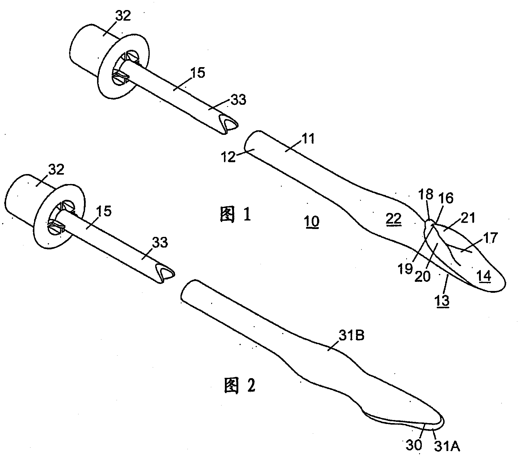
[0116] In the following, specific embodiments of the present invention will be described by way of examples. These examples are the best mode of the present invention in actual use, and are not intended to limit the present invention.

[0117] refer to figure 1The laryngeal mask air guiding device 10 in the disassembled state shown in the first embodiment of the present invention includes an air guiding tube 11 whose proximal end 12 ends with a connector of 15 mm or other specifications. The connecting head is suitable for connecting with conventional breathing anesthesia systems. Near the distal end 13 of the airway is formed a laryngeal pouch or cup 14 which is shaped and contoured to conform to the patient's laryngeal entry site. As used herein, the terms "bladder" and "cup" have the same meaning and both refer to the part on the distal end of the airway of the device and are used to cover the patient's chest when the device is in use. Throat entrance and forms a seal. ...


PUM


Abstract

The invention provides an air guiding device (10) for animals or humans, comprising an air guiding tube (11) having a distal end (13) and a proximal end (12), wherein the air guiding tube (11) The distal portion (13) is surrounded by a non-inflatable laryngeal bladder (14) with a surface adapted to form an anatomical seal at the laryngeal entrance of an animal or human patient, wherein the The surface of the laryngeal pouch (14) is stretched oval, wherein the ratio A / B of the major axis A to the short axis B of the laryngeal pouch (14) is greater than 2±10%.

Description

technical field [0001] The present invention relates to a medical device and method of manufacture thereof, particularly but not limited to laryngeal air-guiding devices. The present invention relates to an anatomically-referenced, simple yet versatile improved air-guiding device. The device is suitable for, but not limited to, delivering oxygen and / or anesthetic gas to a spontaneously breathing human or animal patient, or for intermittent positive pressure ventilation during surgery or rescue. Background technique [0002] Various devices are currently used on spontaneously breathing or intermittent positive pressure ventilation assisted anesthetized patients during recovery from anesthesia to reduce the number of patients requiring intensive care, or to provide clean and Hands-free airway. In the earlier British Patent No. GB2,393,399B (Applicant: Nasir), some devices as described above are listed. By introducing the text of this patent, it forms the main part of the ba...

Claims


Application Information

Patent Timeline
Patent Type & Authority Applications(China)
IPC IPC(8): A61M16/04
CPCA61M2016/0409A61M2016/0493A61D7/04A61M16/0488A61M16/04A61M2016/0415A61M16/0409A61M16/0415A61M16/0493A61M16/0445A61M39/10
Inventor 默罕默德·阿斯拉姆·纳西尔
Owner 默罕默德·阿斯拉姆·纳西尔
Learn More