pedometer

A pedometer and step counting technology, applied in the direction of instruments, counters of additional devices, gymnastics equipment, etc., can solve the problem of being unable to temporarily stop or restart the measurement, unable to know the walking data, and unable to accurately know the walking Data and other issues

Inactive Publication Date: 2011-12-14
CITIZEN WATCH CO LTD +1
View PDF6 Cites 19 Cited by
  • Summary
  • Abstract
  • Description
  • Claims
  • Application Information

AI Technical Summary

Problems solved by technology

[0007] However, in the above-mentioned existing pedometer, since the counting of the section measurement is always carried out continuously like other measurements, if a note or the like is recorded on the spot when the measurement of a certain section is finished, there is a problem that cannot The problem of accurately knowing the walking data of the section that is continuously measured
[0008] In addition, in the existing pedometers with the above-mentioned section measurement function, since any section that can measure the number of steps or distance is limited to one section, for example, when walking multiple times in the same section, if you do not walk in the same section If you take notes on the spot every time you walk in the section, there is a problem that you cannot know the walking data for each section.
Therefore, for example, when walking multiple laps on a predetermined track, in order to compare the number of steps and elapsed time (lap time) of each lap, it is necessa

Method used


Image

  • pedometer
  • pedometer
  • pedometer

Examples


Embodiment approach 1

[0056] (The hardware structure of the pedometer)

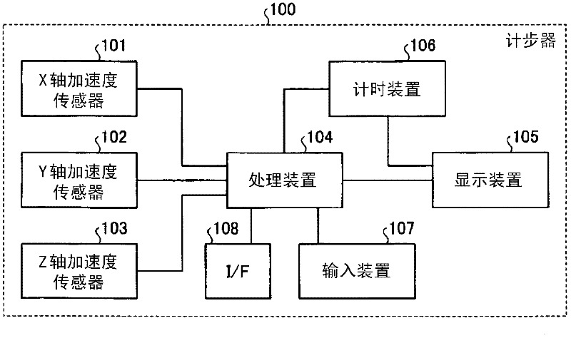
[0057] First, the pedometer according to Embodiment 1 of the present invention will be described. figure 1 It is a block diagram showing the hardware configuration of the pedometer according to Embodiment 1 of the present invention. Such as figure 1 As shown, the pedometer 100 according to Embodiment 1 of the present invention includes a three-axis acceleration sensor capable of detecting accelerations in three different directions (X-axis direction, Y-axis direction, and Z-axis direction). Here, the three-axis acceleration sensor is shown as an X-axis acceleration sensor 101 that detects acceleration in the X-axis direction, a Y-axis acceleration sensor 102 that detects acceleration in the Y-axis direction, and a Z-axis acceleration sensor 103 that detects acceleration in the Z-axis direction. As the acceleration sensor, a known acceleration sensor can be used. The X-axis direction, the Y-axis direction, and the Z-axis dir...

Embodiment approach 2

[0130] (Functional Structure of Processing Device)

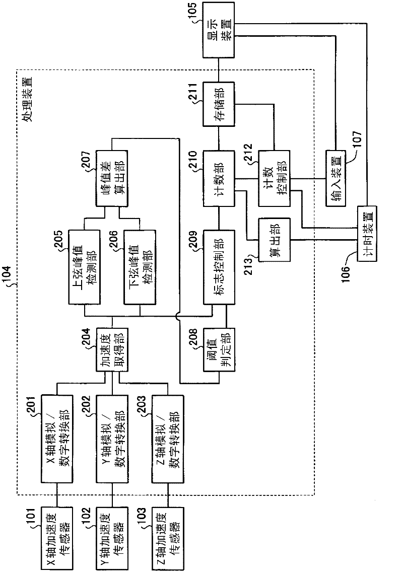
[0131] Next, a pedometer according to Embodiment 2 of the present invention will be described. In the second embodiment, the same parts as those in the above-mentioned first embodiment are denoted by the same symbols, and description thereof will be omitted. Figure 16 It is a block diagram showing the functional configuration of the pedometer processing device according to Embodiment 2 of the present invention.

[0132] Such as Figure 16 As shown, the processing device 104 of the pedometer 100 according to Embodiment 2 of the present invention includes an X-axis analog / digital conversion unit 201, a Y-axis analog / digital conversion unit 202, a Z-axis analog / digital conversion unit 203, and an acceleration acquisition unit. 204, the upper chord peak detection unit 205 and the lower chord peak detection unit 206, the peak difference calculation unit 207 having the function of the calculation mechanism, the threshold value ...


PUM


Abstract

Disclosed is a pedometer which is capable of counting different types of pedometric data and which allows a user to stop the count of any type of pedometric data among the aforementioned types of pedometric data. A pedometer is provided with: a counting unit (210) that counts different types of pedometric data; a storage unit (211) that stores the pedometric data counted by the counting unit; a display device (105) that displays the pedometric data stored in the storage unit; and an input device (107) that designates pedometric data for which counting is to be stopped. The user can, at his or her own will, start or stop the counting of any type of pedometric data among the different types of pedometric data.

Description

technical field [0001] The present invention relates to pedometers. Background technique [0002] The pedometer detects the vertical acceleration of the pedestrian through the acceleration sensor, counts the number of steps (body movement) based on the change of the detected value, and displays the counted number of steps numerically. In recent years, pedometers can not only display the number of steps, but also switch and display multiple information such as calories burned, fat burned, walking distance, and walking time. In addition, not only the number of steps of the current day can be displayed, but also the number of steps in the past few days can be displayed together, or the cumulative number of steps for multiple days can be displayed. [0003] In addition, among the conventional pedometers, there is a pedometer that has a section measurement function different from the normal step count function, and this section measurement function is used when measuring the num...

Claims


Application Information

Patent Timeline
IPC IPC(8): G06M3/00A61B5/22A63B23/04G01C22/00
CPCG01C22/006
Inventor 中村忠三浦淳千叶隆广
Owner CITIZEN WATCH CO LTD
Why Eureka
Try Eureka