Oscillating mechanism of tower-type fan

A fan and tower-type technology, applied in the field of shaking head mechanism, can solve the problems of power cord damage, low safety, fire, etc., and achieve the effect of reducing internal friction damage, eliminating cross-winding, and simple assembly structure

Inactive Publication Date: 2013-04-17
MIDEA GRP CO LTD
View PDF4 Cites 0 Cited by
  • Summary
  • Abstract
  • Description
  • Claims
  • Application Information

AI Technical Summary

Problems solved by technology

[0002] The oscillating mechanism of the tower fan in the present technology relies on the one-way synchronous motor installed at the bottom of the tower fan to push the fan body to move through the planar four-bar linkage mechanism. This common structure consists of a one-way synchronous motor, crank, connecting rod, support Plate, fixed plate, center shaft, shaft sleeve, slip ring, etc.; the structure of the oscillating head mechanism is complex, with many components and difficult assembly. At the same time, the power cord is easily in contact with the movable connecting rod, which increases the probability of power cord damage. And fire, the safety is not high; at the same time, the rotating part relies on the friction between the plastic parts and the plastic parts, the wear is relatively large, and the precision of the mold making is high; and the existing shaking head mechanism has poor bearing capacity and cannot drive the water-cooled evaporation tower with a water tank. fan

Method used


Image

  • Oscillating mechanism of tower-type fan
  • Oscillating mechanism of tower-type fan

Examples


Embodiment Construction

[0015] The patent of the present invention will be further described below in conjunction with the accompanying drawings and examples of implementation.

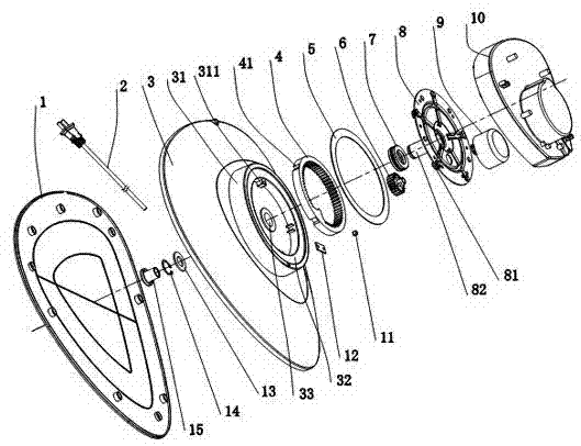
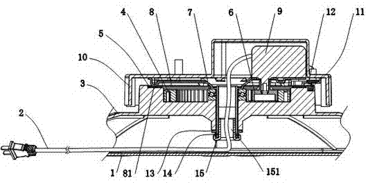
[0016] like figure 1 , 2 As shown, the present invention is an oscillating mechanism of a tower fan, which includes a support plate 10 that drives the body of the tower fan to rotate, a fixed plate 8 installed on the support plate 10, a synchronous motor 9 installed on the fixed plate 8 and Hall sensor 12, driving gear 6 installed on the extension shaft of synchronous motor 9, driven gear 4 meshed with driving gear 6, base 3 for installing driven gear 4, magnet 11 installed in the groove of base 3 And the bottom plate 1 installed on the base 3; the fixed plate 8 is provided with a hollow shaft 82, the center of the base 3 is provided with a fixed hole 33, the lower end of the hollow shaft 82 is inserted into the fixed hole 33 and Axial positioning; the Hall sensor 12 is installed on the support plate 10 and cooperates with...


PUM


Abstract

The invention relates to an oscillating mechanism of a tower-type fan. The oscillating mechanism is characterized by comprising a support plate for driving the body of the tower-type fan to rotate, a fixed plate installed on the support plate, a synchronous motor and a Hall sensor installed on the fixed plate, a driving gear installed on a projecting shaft of the synchronous motor, a driven gear meshed with the driving gear, a base for installing the driven gear, a magnet installed in a slot of the base and a bottom plate installed on the base, wherein the fixed plate is provided with a hollow rotating shaft, the centre of the base is provided with a fixed hole, the lower end part of the hollow rotating shaft inserts in the fixed hole and is positioned in an axial direction; and the Hall sensor is installed on the support plate and is mutually coordinated with the magnet. The oscillating mechanism has the advantages of more stable operation, no cross-intertwined internal power wires, simpler assembly structure, reduced internal friction damage and low cost and the like.

Description

technical field [0001] The patent of the present invention relates to the technical field of fans, in particular to an oscillating mechanism of a tower fan. Background technique [0002] The oscillating mechanism of the tower fan in the present technology relies on the one-way synchronous motor installed at the bottom of the tower fan to push the fan body to move through the planar four-bar linkage mechanism. This common structure consists of a one-way synchronous motor, crank, connecting rod, support Plate, fixed plate, center shaft, shaft sleeve, slip ring, etc.; the structure of the oscillating head mechanism is complex, with many components and difficult assembly. At the same time, the power cord is easily in contact with the movable connecting rod, which increases the probability of power cord damage. And fire, the safety is not high; at the same time, the rotating part relies on the friction between the plastic parts and the plastic parts, the wear is relatively large,...

Claims


Application Information

Patent Timeline
Patent Type & Authority Patents(China)
IPC IPC(8): F04D25/10
CPCF04D25/10
Inventor 丁凡聂勇严木火王斌艾耀平涂剑
Owner MIDEA GRP CO LTD
Why Eureka
Try Eureka